●
Rail mounting according to DIN35 / TS35 standard,
●
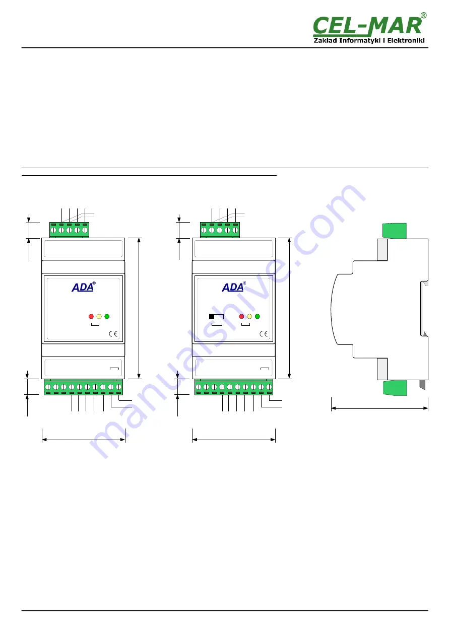
Dimensions (W x D x H) 53mm x 62mm x 90mm.
2.2. DESCRIPTION
ADA-4020 converts RS485/RS422 standard to Current Loop without interfering with format of transmitted data with maximum baud
rate of 38,4kbps via 2-pair of twisted pair.
The converter has screw terminal blocks for connection of RS485/422, Current Loop networks and power supply. This device use
RX+, RX-, TX+, TX- signals for operating.
Over-voltage protection was made on base safety diodes and fuses on each RS485/RS422 and Current Loop lines.
To RS485/RS422 bus, created on the base ADA-4020, can be connected: 32 devices operate in half duplex (query / response) mode
on 2-wires or 4-wires bus or full duplex on 4-wires bus.
To Current Loop bus, created on the base ADA-4020, can be connected
- 2 devices operating in half duplex or full duplex mode in point-to-point topology,
- 15 devices operating in half duplex mode in multipoint topology 'current loop network'.
The converter has an internal low-energy surge protection for each line of Current Loop interface. However, for the lightning protection
should be used external lightning arresters such as the typical phone line protection.
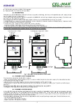
Fig 1. ADA-4020 view and location of SW1 switch
2.3. CURRENT LOOP TRANSMITTER
The Current Loop transmitter at ADA-4020 is made as:
- active, on the base power source generate c/- 20mA or 0-20mA (depend on converter's version). The transmitter has short
circuit protection on TX+ and TX- lines.
- passive 0-20mA, on the base transistor, has also short circuit protection on TX+ and TX- lines.
The transmitter of Current Loop 0-20mA can work as ACTIVE or Passive, the selection is made by the TX switch on the front panel
(see Fig.1).
The passive transmitter can be used only for creation of current loop bus, see point 3.5.
The diagram of the transmitter & receiver is shown on figure below.
2.4. CURRENT LOOP RECEIVER
In the ADA-4020 converter has been used passive RX receiver consisting of optoisolator (optical coupler) and protective elements.
The receiver circuit has RX+, RX- terminals as well as the terminal marked as RX-*. In the circuit with RX-* terminal has been used
additional resistor (1000 ohms or 560 ohms depend on the converter version) to reduce power in the case of connecting the receiver
to transmitter which has NOT short circuit current limit to 20mA.
The RX red LED on front panel of the converter is a signalization of NO current flow through optocoupler. This LED is ON when it is:
- not connect transmitter to receiver,
- wrong connection of transmitter to receiver,
- broken connection of transmitter to receiver.
4
ADA-4020
62mm
Power Supply
10 - 30 VDC
90
m
m
53mm
10
m
m
10
m
m
(SW1)
G
N
D
T
X
+
/A
T
X
-
/B
R
X
+
R
X
-
(RS485/RS422)
RS-485 4-wires
or RS-422
RS-485
2-wires
Current Loop
Interface
N
C
N
C
N
C
T
X
+
T
X
-
R
X
+
R
X
+
*
R
X
-
(CURRENT LOOP)
V
-
V
+
10 – 30
VDC
PWR
TX
RX
ADA-4020
RS-485/RS-422 to CURRENT LOOP
CONVERTER
CL
ACT
PSV
TX
90
m
m
53mm
10
m
m
10
m
m
(SW1)
G
N
D
T
X
+
/A
T
X
-
/B
R
X
+
R
X
-
(RS485/RS422)
N
C
N
C
N
C
T
X
+
T
X
-
R
X
+
R
X
+
*
R
X
-
(CURRENT LOOP)
V
-
V
+
10 – 30
VDC
PWR
TX
RX
ADA-4020
RS-485/RS-422 to CURRENT LOOP
CONVERTER
CL
ACT
PSV
TX
Active trans/-20mA
Active/passive transmitter 0 / 20mA
RS-485 4-wires
or RS-422
RS-485
2-wires
Power Supply
10 - 30 VDC
Current Loop
Interface

