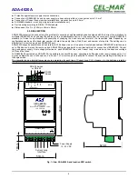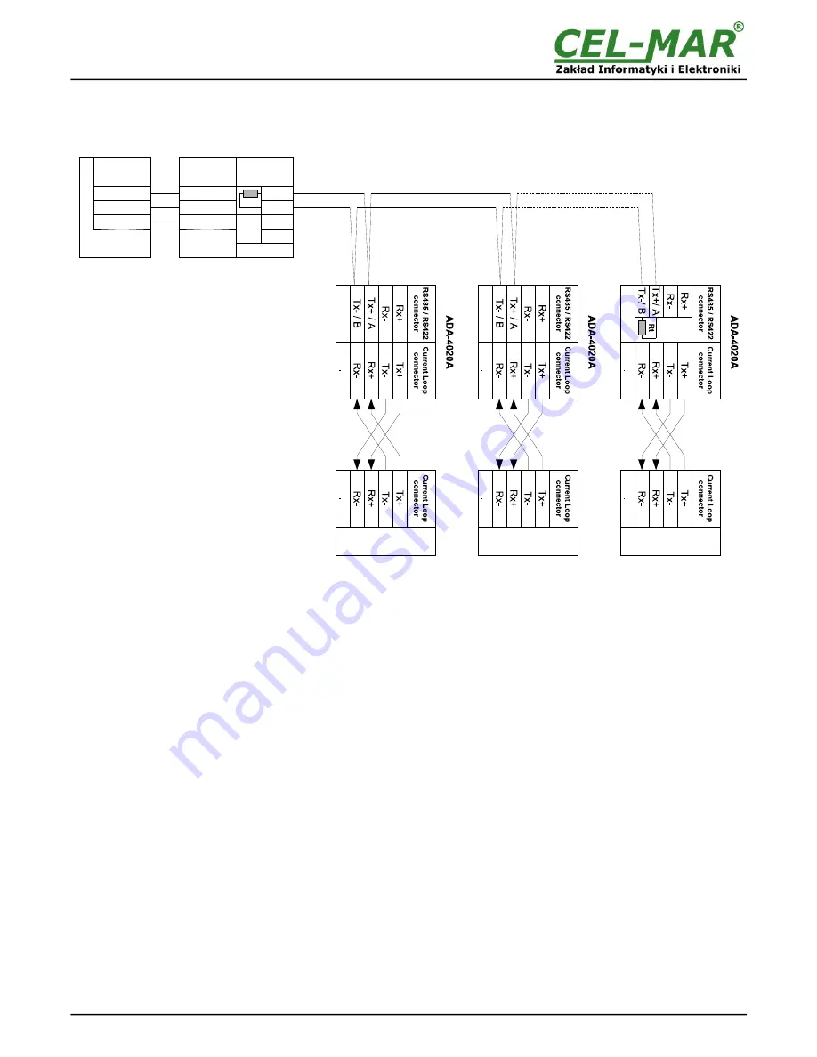
3.3.2. CONNECTION TO RS485 (2-WIRES) BUS
Fig 7. Example connection of ADA-4020A to RS485 2-wires bus and galvanic separation of SLAVE device.
3.3.3. GND TERMINALS CONNECTION
Connection of GND terminals of RS485/422 interfaces, devices connected to RS485/422 bus, should be done in the case of a
potential difference of the signals grounds on interfaces RS485 / RS422, which prevents proper data transmission.
Cannot connect to the GND terminal - cables screens, PE circuit of electrical installation, signals grounds of other devices.
3.3.4. LINE TERMINATION
The application of Line Termination (terminator) Rt = 120 ohms will reduce electrical reflection in data line at high baud rate. It is not
needed below 9600Bd. The Line Termination resistor should be used if the distance is over 1000m @ 9600Bd or 700m @ 19200Bd
transmission, the resistor can be necessary if there are problems with the transmission correctness. Example connection of Rt are
shown on Fig. 6 & 7. Resistor Rt = 120
W
, 5%, 0.25W of a 2 pc. is complete with the device ADA-4020A.
3.3.5. CONNECTION OF CURRENT LOOP DEVICES
The connections of SLAVE devices with current loop interface to ADA-4020A are shown on Fig.6 & Fig.7.
3.4. POWER SUPPLY
The power supply to ADA-4020A should be DC (regulated) from the scope 10 V= to 30V= and nominal power more then 2W. The
power cable from DC power supplies to the device must not be longer than 3m. Observe the polarity, connect positive (+) of DC power
supplies to V+ and negative (-) end to V- terminal. The ADA-4020A has the protection from opposite connection power supply.
If after power, on the front panel is not lit green LED PWR, check the power connection (polarity).
4. ACTIVATION
Converter can be powered after proper connection according to steps above.
If connection was made properly green LED PWR on front panel of converter should light, if not check polarization of power
connection and if RX LED is lighted check connection correctness of Current Loop CLO transmitter circuit. Lighting this LED indicates
non flow of current through optocoupler in receiver circuit.
During correctness data transition via the converter the LEDs Tx and Rx should blinking.
7
ADA-4020A
(5) GND
GND
(2) Rx
(3) Tx
ADA-I1040
GND (5)
Tx (2)
Rx (3)
Rt
Rx+
Rx-
Tx+/ A
Tx-/ B
RS485(4W) bus
9600Bd/8/O/1
PC or
MASTER device
CL
SLAVE
2400Bd/8/N/2
SLAVE
19200/Bd/7/N/2
SLAVE
9600Bd/8/E/1
CL
CL
RS232
connector
DB-9F/DCE
RS485 / RS422
connector
RS232
connector
DB-9M/DTE
Summary of Contents for ADA-4020A
Page 15: ...15 ADA 4020A...

