background image

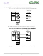
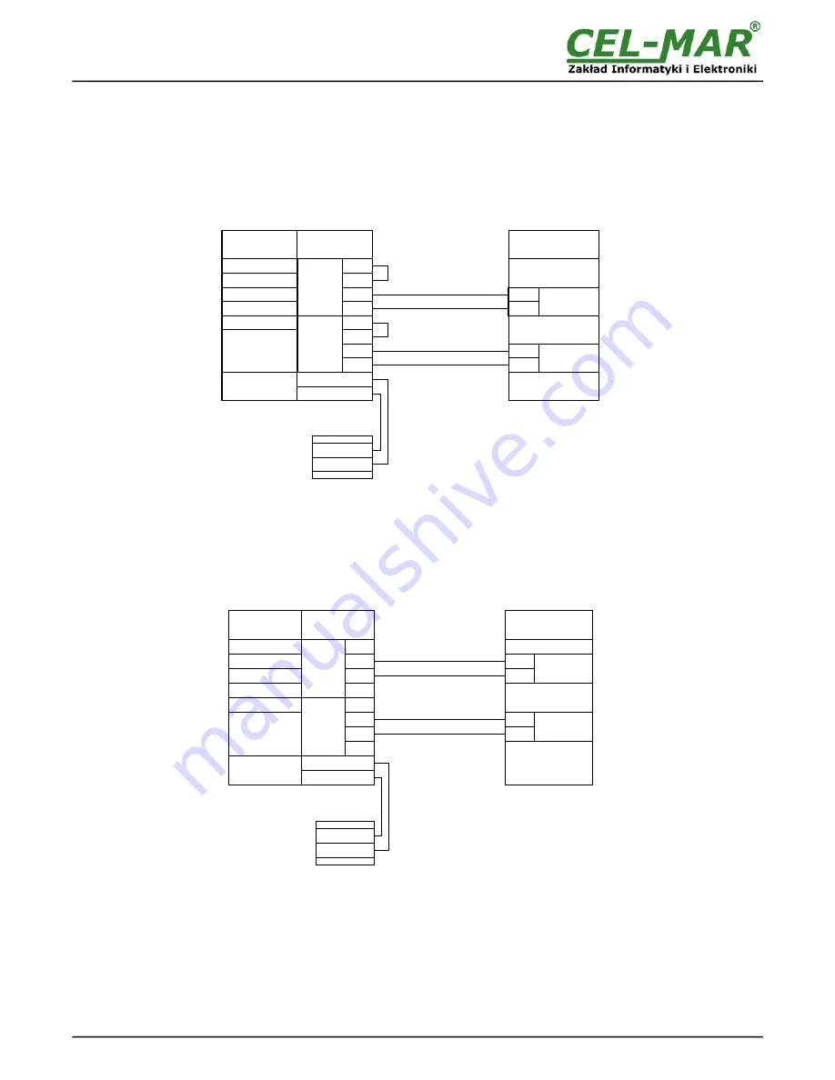
3.4. CONNECTION TO CURRENT LOOP DEVICE 

Current Loop line is connected to TX+, TX-, I1+, I1-, RX+, RX-, I2+, I2- terminals of converter as below.

3.4.1. CONNECTION TO DEVICE WITH PASSIVE TRANSMITTER & PASSIVE RECEIVER

Fig 8. Example connection of device with passive transmitter and passive receiver to ADA-4021

3.4.2. CONNECTION TO DEVICE WITH ACTIVE TRANSMITTER & ACTIVE RECEIVER

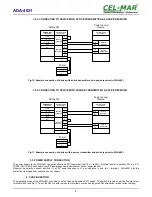
Fig 9. Example connection of device with active transmitter and  active receiver to ADA-4021

7

ADA-4021

ADA-4021

V +

V -

Power

Tx+

Tx-

Rx+

Rx-

Current Loop 

Device

I1 +

I1 -

I2 +

I2 -

Rx +

Current Loop 

connector

Tx +

Tx -

Rx -

V -
V+

Tx- / B-

Rx-

RS485/RS422

connector

GND

Tx+ / A

Rx+

Active 

Transmitter

Active 

Receiver

Passive 

Transmitter

Passive 

Receiver

Current Loop 

connector

ADA-4021

V +

V -

Power

V -

V +

Tx+

Tx-

Rx+

Rx-

Current Loop 

Device

I1 +

I1 -

I2 +

I2 -

Rx +

Tx +

Tx -

Rx -

Tx- / B-

Rx-

GND

Tx+ / A

Rx+

RS485/RS422

connector

Current Loop 

connector

Passive 

Transmitter

Passive 

Receiver

Active 

Transmitter

Active 

Receiver

Current Loop 

connector

Summary of Contents for ADA-4021

Page 1: ...User manual ADA 4021 RS 485 RS 422 to Current Loop Converter 1 io_ada 4021_v0 13_en ADA 4021 Copyright 2001 2017 CEL MAR sp j...

Page 2: ...ION TO RS485 BUS 6 3 3 1 4 WIRE CONNECTION 6 3 3 2 2 WIRE CONNECTION 6 3 3 3 LINE TERMINATION 6 3 4 CONNECTION TO CURRENT LOOP DEVICE 7 3 4 1 CONNECTION TO DEVICE WITH PASSIVE TRANSMITTER PASSIVE RECE...

Page 3: ...g the power supply circuit voltage Do not carry out the assembly or disassembly of the device if it is enabled This may result to short circuit and damage the device The device can not be used for app...

Page 4: ...tion of telephone line for the lightning protection of lines Fig 1 View 2 3 CURRENT LOOP TRANSMITTER The Current Loop transmitter in the ADA 4021 was made as a passive 0 20mA having low energy short c...

Page 5: ...rcuit device that generates large impulse interference such as transmitters contactors 3 1 ASSEMBLING The ADA 4021 enclosure is adapted to assembly on TS 35 DIN35 rail To install converter should the...

Page 6: ...INE TERMINATION The application of Line Termination terminator Rt 120 W will reduce electrical reflection in data line at high baud rate It is not needed below 9600Bd should be used the Line Terminati...

Page 7: ...le connection of device with active transmitter and active receiver to ADA 4021 7 ADA 4021 ADA 4021 V V Power Tx Tx Rx Rx Current Loop Device I1 I1 I2 I2 Rx Current Loop connector Tx Tx Rx V V Tx B Rx...

Page 8: ...V terminal ADA 4021 has the protection from opposite connection power supply 4 CONFIGURATION The operating mode of the ADA 4021 converter is set by the use 6 position SW1 switch This switch is locate...

Page 9: ...connection was made properly green LED PWR on front panel of converter should light if not check polarization of power connection If the red LED RX is light check correctness of connection transmittin...

Page 10: ...ugh Current Loop interface Electrical Parameters Power requirements 10 24 30 V DC Power cable Recommended length of power cable 3m Power 2W Protection from reverse power polarization YES Galvanic isol...

Page 11: ...11 ADA 4021...

Page 12: ...ta transmission converters with interface RS232 RS485 RS422 USB Current Loop Fibre Optic Converters and Ethernet or Wi Fi Please contact us to tell how you like our products and how we can satisfy you...

Reviews: