background image

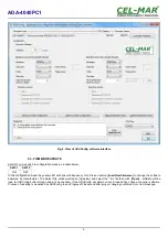
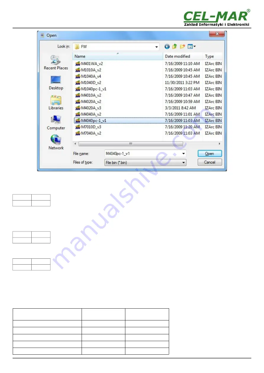
Fig. 9. Selection of firmware file

During loading software the yellow LED located beside SW1 micro-switch will blink, showing data flow to the converter. If the software

was loaded correctly yellow LED will be blink with frequency 1 Hz.

After that, set microswitch SW1 to run mode as shown in the table below.

SW1-1

SW1-2

OFF

OFF

In the run mode the yellow LED (located near the SW1), will turn off.

5.4. EMERGENCY FIRMWARE UPDATE

In case of the unsuccessful update of the converter software, try again according to description in the above point. If the update is still

incorrect use emergency firmware update. Set SW1 microswitch mode as in the table below.

SW1-1

SW1-2

ON

ON

After microswitch setting, should be restarted ADA-4040PC1, by turning OFF and then ON the power supply. The yellow LED will light

continuously and the converter will be in Emergency Firmware Update mode. Now follow the description in the above point.

After successful software update, set microswitch SW1 to the run mode as shown in the table below.

SW1-1

SW1-2

OFF

OFF

In the run mode the yellow LED (located near the SW1), will turn off.

5.5. FACTORY DEFAULT 

In case of faulty functioning of ADA-4040PC1, like:

- no communication in the configuration mode,

- transmission errors on RS485/422 bus,

can be restored the factory default setting of the converter internal registers.

Factory default

Parameter

ASCII interface

RS485/RS422

RTU interface

RS485/RS422

Baud rate

9600bps

9600bps

Data bits

8

8

Parity

Non

Non

Stop bits

1

1

Interval between frames in bytes

4

4

10

ADA-4040PC1

Summary of Contents for ADA-4040PC1

Page 1: ...User manual ADA 4040PC1 MODBUS ASCII to MODBUS RTU converter 1 io_ada 4040pc1_v1 03_en ADA 4040PC1 Copyright 2001 2017 CEL MAR sp j...

Page 2: ...485 NETWORK CONNECTION 6 3 3 1 RS485 4W BUS CONNECTION 6 3 3 2 RS485 2W BUS CONNECTION 7 3 3 3 GND TERMINALS CONNECTION 7 3 3 4 LINE TERMINATION Rt 7 3 3 5 SLAVE DEVICE CONNECTION 7 3 4 POWER SUPPLY C...

Page 3: ...twork is only after disconnecting the power supply circuit voltage Do not carry out the assembly or disassembly of the device if it is enabled This may result to short circuit and damage the device Th...

Page 4: ...on RS422 485 bus and increases its reliability ADA 4040PC supports the asynchronous baud rate up to 230 4 kbps through four or two pairs of twisted pair cables connected to screw terminals The convert...

Page 5: ...nverter should be mounted on the rail upper part of the cover then press bottom part to hear characteristic Click sound 3 2 COMPUTER CONNECTION To connect ADA 4040PC1 to computer equipped with RS 232...

Page 6: ...separation of SLAVE device 6 ADA 4040PC1 GND USB PC USB Rx Rx Tx A Tx B Tx A Tx B Rx Rx Tx A Tx B GND Rx Rx GND ADA I9140 ADA 4040PC1 USB connector RS485 RS422 connector USB connector RTU RS485 RS422...

Page 7: ...of SLAVE devices to ADA 4040PC1 are shown on fig 5 and fig 6 3 4 POWER SUPPLY CONNECTION To connect power supply to the converter should have DC power supplies regulated output voltage from 10 V to 30...

Page 8: ...n modes SW1 1 SW1 2 Mode OFF OFF Run ON OFF Configuration OFF ON Factory default Turning OFF and ON the power of the converter the configuration will be set to factory default ON ON Emergency firmware...

Page 9: ...d New Firmware to change the software delivered by manufacturer The Select File window will open fig below and select the bin file then click Open software will be load to ADAConfig buffer storage and...

Page 10: ...After microswitch setting should be restarted ADA 4040PC1 by turning OFF and then ON the power supply The yellow LED will light continuously and the converter will be in Emergency Firmware Update mod...

Page 11: ...n case of misrepresent bytes in transmitted sign This counter will not work in case of disable control parity To check those counters press the button Read transmission errors and to delete zeroing of...

Page 12: ...ds on baud rate Max number of connected device Up to 32 devices Baud rates bps 300 600 1200 1800 2400 4800 7200 9600 14400 19200 28800 38400 57600 76800 115200 230400 Data formats Data bits 5 6 7 8 Pa...

Page 13: ...5 RS 422 ASCII and RS 485 RS 422 RTU Electromagnetic compatibility Resistance to disruptions according to the standard PN EN 55024 Emission of disruptions according to the standard PN EN 55022 Safety...

Page 14: ...14 ADA 4040PC1...

Page 15: ...15 ADA 4040PC1...

Page 16: ...data transmission converters with interface RS232 RS485 RS422 USB Current Loop Fibre Optic Converters and Ethernet or Wi Fi Please contact us to tell how you like our products and how we can satisfy y...

Reviews: