background image

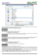
Fig 9. Selection of firmware file

During loading software the yellow LED located beside SW1 micro-switch will blink, showing data flow to the converter. If the software
was loaded correctly yellow LED will be blink again with frequency 1 Hz.
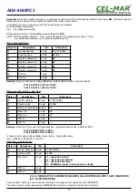
After that, set microswitch SW1 to RUN mode as shown in the table below.

SW1-1

SW1-2

OFF

OFF

In the RUN mode the yellow LED (located near the SW1), will turn off.

5.5. EMERGENCY FIRMWARE UPDATE

In case of the unsuccessful update of the converter software, try again according to description in the above point. If the update is still
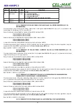
incorrect use emergency firmware update. Set SW1 microswitch mode as in the table below.

SW1-1

SW1-2

ON

ON

After microswitch setting, should be restarted ADA-4040PC3, by turning OFF and then ON the power supply. The yellow LED will light
continuously and the converter will be in Emergency Firmware Update mode. Now follow the description in the above point.
After successful software update, set microswitch SW1 to the RUN mode as shown in the table below.

SW1-1

SW1-2

OFF

OFF

In the RUN mode the yellow LED (located near the SW1), will turn off.

6. DATA TRANSMISSION DIAGNOSTICS

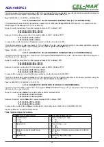
To readout diagnostics, the SW1 microswitch should be set to the configuration mode.

SW1-1

SW1-2

ON

OFF

In the configuration mode the yellow LED will blink with frequency 1Hz.
Correctness of transmission proceed on  SUN(RS485) and RTU(RS485) interfaces,  can be checked by readout the errors list by

ADAConfig 

Software from the converter memory. Frames error counter will be increased, in case of: improper speed set compared to

real  speed   of data  transmission.   Parity  error counter   will be  count  the  errors  which   can  arise  in  case  of  misrepresent   bytes  in
transmitted sign. This counter will not work in case of disable control parity
To check those counters press the button  

[Read transmission errors],

  and to delete (zeroing of counters in the memory of the

converter)  press  

[Delete   transmission   errors].  

In  case   of  parity   errors   or  frame  errors,  should   be  checked  the   ADA-4040PC3

converter's configuration and correctness connection of RS485 bus to RTU and SUN converter's ports.
After finishing the diagnostics, the SW1 microswitch should be set to the run mode as shown in the table below.

10

ADA-4040PC3

Summary of Contents for ADA-4040PC3

Page 1: ...User manual ADA 4040PC3 SunMaster to MODBUS RTU protocol converter 1 io_ada 4040pc3_v1 04_en ADA 4040PC3 Copyright 2001 2020 CEL MAR sp j...

Page 2: ...EFERENCES HOLDING REGISTERS 12 8 2 FRAME STRUCTURE OF MODBUS RTU PROTOCOL 13 8 3 USED FUNCTIONS OF MODBUS RTU PROTOCOL 13 8 3 1 FUNCTION 0x03 0x04 READOUT VALUE MEASUREMENTS AND STATUS FROM INVERTER 1...

Page 3: ...plete disable from the supply network is only after disconnecting the power supply circuit voltage Do not carry out the assembly or disassembly of the device if it is enabled This may result to short...

Page 4: ...cables connected to screw terminals The converter use RX RX TX A TX B lines for functioning It is possible to connect 32 devises to RS485 RS422 network constructed on base of ADA 4040PC3 working at th...

Page 5: ...apted to assembly on TS 35 DIN35 rail To install the converter should be mounted on the rail upper part of the cover then press bottom part to hear characteristic Click sound 3 2 COMPUTER CONNECTION T...

Page 6: ...GND USB PC USB Rx Rx Tx A Tx B Tx A Tx B Rx Rx Tx A Tx B GND Rx Rx GND ADA I9140 ADA 4040PC3 USB connector RS485 RS422 connector USB connector RTU RS485 RS422 connector SUN RS485 RS422 connector RS48...

Page 7: ...power on after properly connection according to section above If after connection power supply on front panel will not light green led PWR check correctness of power supply connecting polarization Whe...

Page 8: ...SW1 2 ON OFF In the configuration mode yellow LED located by SW1 micro switch will blink with frequency 1 Hz Start the ADAConfig Software and make the configuration of transmission parameters for each...

Page 9: ...as shown in the table below SW1 1 SW1 2 OFF OFF In the RUN mode the yellow LED located near the SW1 will turn off 5 4 FIRMWARE UPDATE Set SW1 micro switch to configuration mode as in table below SW1 1...

Page 10: ...low SW1 1 SW1 2 OFF OFF In the RUN mode the yellow LED located near the SW1 will turn off 6 DATA TRANSMISSION DIAGNOSTICS To readout diagnostics the SW1 microswitch should be set to the configuration...

Page 11: ...OCOL ADA 4040PC3 protocol converter allows connecting Inverters with SunMaster Soladin protocol as SLAVE to RS485 MODBUS RTU bus The length of RS485 bus can be extended by the use of ADA 4040 repeater...

Page 12: ...6 bit open terminal voltage R 16 bit register 30015 14 Hi 0x00 Rac Phase network impedance measurement R 16 bit register 8 1 2 REGISTERS ACTUAL VALUES MEASUREMENTS AND CONDITION INVERTER READOUT BY FU...

Page 13: ...04 are used for readout of status and measurement values from the INVERTER The measurement values readout form MODBUS RTU register is presented by a 16 bit register The registers with the measurement...

Page 14: ...Hi 11 04 00 02 00 01 CRCLo CRCHi Response with register value Usol Byte no Designation Size Value hex 00 Inverter address 1 byte 11 11 to F7 01 Function code 1 byte 03 04 02 Number of data bytes N byt...

Page 15: ...ue d n div_MeasurmentValue quot div_MeasurmentValue rem Query of register Eac Byte no Designation Size Value hex 00 Inverter address 1 byte 11 11 to F7 01 Function code 1 byte 03 04 02 Registry addres...

Page 16: ...olar panel current Isol from registry address 40004 address 30004 11 03 00 03 00 01 CRCLo CRCHi 11 04 00 03 00 01 CRCLo CRCHi Readout of solar panel current Isol from registry address 40004 address 30...

Page 17: ...ve algorithms using the appropriate factor value DW for register Iac see the Table of divider values DW above Iac 0x00DF 223 100 2 23 A AC 8 3 1 8 READOUT OF POWER VALUE Pac ALTERNATING VOLTAGE NETWOR...

Page 18: ...address 30012 11 03 00 08 0B 02 CRCLo CRCHi 11 04 00 08 0B 02 CRCLo CRCHi Readout of inverter s running time Ton from registry address 40012 address 30012 11 03 04 00 00 F0 DF CRCLo CRCHi 11 04 04 00...

Page 19: ...nown function 02 unknown data address 03 unknown data value 04 SunMaster inverter not respond or is faulty 03 CRC Lo 1 Byte 04 CRC Hi 1 Byte 9 VERSIONS ADA 4040PC3 Order example Product Symbol ADA 404...

Page 20: ...70 C Casing Dimensions 53 x 90 x 62 mm Material PC ABS Degree of casing protection IP40 Degree of terminal protection IP20 Weight 0 10 kg According to standard DIN EN50022 DIN EN43880 Location during...

Reviews: