background image

1. GENERAL INFORMATION

Thank you for your purchase of 

CEL-MAR Company

 product. This product has been completely tested and is covered by a two year

warranty on parts and operation from date of sale. 

If any questions or problems arise during installation or use of this product, please do not hesitate to contact Technical Support at +48

41 362-12-46 or e-mail support@cel-mar.pl.

1.1. WARRANTED INFORMATION 

ADA-4040PC6  

converter is covered by a two year warranty from date of sale.    In case of being damaged it will be repair or the

damaged component will be replace. The warranty does not cover damage caused from improper use, materials consumption or any

unauthorized changes. If the product does not function (is damaged), or not operate in accordance with the instructions, will be

repaired or replaced.
All warranty and no warranty repairs must be returned with paid transport and insuring to the 

CEL-MAR Company.

CEL-MAR Company 

under no circumstances won't be responsible for ensuing damage from improper using the product or as a result

of random causes: the lightning discharge, the flood, the fire and the like.

CEL-MAR Company

 is not be held responsible for damages and loss including: loss of profits, loss of data, pecuniary losses ensuing

from using or the impossibility of using this product.
In specific cases

 CEL-MAR Company

 discontinue all warranties and in particular do not follow the user manual and do not accept

terms of warranty by the user.

1.2. GENERAL CONDITIONS FOR SAFE USE

The device should be installed in a safe and stable places (eg, electroinstallation cabinet), the powering cable should be arranged  so

as not to be exposed to trampling, attaching, or pulling out of the circuit. 

Do not put device on the wet surface.

Do not connect devices for nondescript powering sources,

Do not damage or crush powering wires.

Do not make connection with wet hands.

Do not adapt, open or make holes in casings of the device!

Do not immerse device in water or no other liquid.

Do not put the fire opened on device sources: candles, an oil lamps and the like.

Complete disable from the supply network is only after disconnecting the power supply circuit voltage. 

Do not carry out the assembly or disassembly of the device if it is enabled. This may result to short circuit and damage the device.

The device can not be used for applications that determine human life and health (eg. Medical). 

1.3. CE LABEL

The   CE   symbol   on   the   device   CEL-MAR   means   compatibility   with   electromagnetic   compatibility   Electromagnetic
Compatibility Directive 

EMC 2014/30/WE.


The declaration of conformity is delivered with purchased device.

1.4. ENVIRONMENTAL PRESERVATION

This sign on the device inform about putting expended device with other waste materials. Device should send to the

recycling. (In accordance with the act about the Electronic Appliance Expended from day 29 of July 2005)

1.5. SERVICE AND MAINTENANCE

Converter ADA-4040PC6 does not require the servicing and maintenance.

Technical support is available at 48 41 362-12-46 in 8.00-16.00, from Monday to Friday or e-mail 

support@cel-mar.pl

.

1.6. PACK CONTENTS

ADA-4040PC6 converter; User Manual; CE declaration; Line terminators 120

W;

 CD with ADAConfig software.

2. PRODUCT INFORMATION

2.1. PROPERTIES

Protocol conversion NMEA0183 to MODBUS-RTU and inversely,

Baud rate and data format conversion between NMEA0183 and MODBUS-RTU ports,

Operating on 2 or 4 wire buses in RS485/RS422 standard,

Baud rate setted on RS485/RS422 interfaces (bps): 300, 600, 1200, 1800, 2400, 4800, 7200, 9600, 14400, 19200, 28800, 38400, 

57600, 76800, 115200, 230400,

Data format setted on RS485/RS422 interfaces: Data bit: 5, 6, 7, 8; Parity: None, Odd, Even; Number of stop bits: 1, 2,

Power supply 10 - 30 VDC stable min. 2W,

~3kV= optoisolation in signal channel between RS485/RS422 (MODBUS-RTU) and RS485/RS422 (NMEA0183),

1kV= or 3kV= galvanic isolation between RS485/RS422 (MODBUS-RTU), RS485/RS422 (NMEA0183) interfaces and power 

supply (depend on version),

Connection RS485/RS422 network and power supply via screw terminal block 2.5 mm

.

Implemented short circuit protection and over-voltage protection on RS485 / RS422 network,

Implemented protection against power supply reverse connection,

Cover compatible with DIN 43880 standard– mounting in typical electro-installation unit,

Cover adapt to rail mounting according to DIN35 / TS35 standard,

Cover dimensions (W x D x H) 53mm x 62mm x 90mm,

3

ADA-4040PC6

Summary of Contents for ADA-4040PC6

Page 1: ...User manual ADA 4040PC6 NMEA0183 to MODBUS RTU Protocol Converter 1 ADA 4040PC6 Copyright 2001 2022 CEL MAR sp j io_ada 4040pc6_v1 05_en...

Page 2: ...IMPLEMENTATION OF MODBUS RTU PROTOCOL 10 8 1 MODBUS REGISTERS TABLE OF STANDARD NMEA0183 SENTENCE 10 8 1 1 CONVERTER MODBUS REGISTERS TABLE IN READOUT BY FUNCTION 04 3X REFERENCES INPUT REGISTERS 10...

Page 3: ...ply network is only after disconnecting the power supply circuit voltage Do not carry out the assembly or disassembly of the device if it is enabled This may result to short circuit and damage the dev...

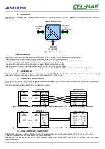
Page 4: ...bles connected to screw terminals The converter use RX RX TX A TX B lines for functioning It is possible to connect 32 devises to RS485 RS422 network constructed on base of ADA 4040PC6 working at the...

Page 5: ...sound 3 2 COMPUTER CONNECTION To connect ADA 4040PC6 to computer is needed additional converter e g ADA I9141 USB to RS485 RS422 converter connected to NMEA 5 pin connector port of the converter Typic...

Page 6: ...re bus and FURUNO GP 150 NMEA0183 6 ADA 4040PC6 RS485 RS422 connector RS485 4W BUS 19200Bd 8 N 1 MODBUS RTU MASTER MODBUS RTU DEVICE SLAVE 2 MODBUS RTU SLAVE 1 MODBUS RTU GND Rt Rt Rx Rx Tx A Tx B RS4...

Page 7: ...lling of normal operating mode RUN Blinking at frequency 1 Hz signalling of configuration mode or data flow of software to the converter Blinking at frequency 2 Hz signalling of factory default mode L...

Page 8: ...3 port baud rate kbps 0 3 0 6 1 2 1 8 2 4 4 8 7 2 9 6 14 4 19 2 28 8 38 4 57 6 76 8 115 2 230 4 number of data bites 5 6 7 8 control parity no control parity control control of none parity number of s...

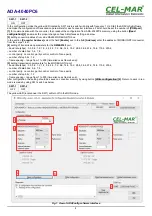
Page 9: ...after proper changing confirmed by correct message Fig 8 Selection of firmware file During loading software the yellow LED located beside SW1 micro switch will blink showing data flow to the converte...

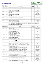
Page 10: ...arator of NMEA0183 port from MODBUS RTU port ADA 4040PC6 reads data from NMEA0183 device and properly processed write them to registers of MODBUS RTU protocol described in pt IMPLEMENTATION OF MODBUS...

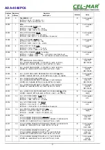
Page 11: ...2 30010 9 GLL LONGITUDE 00636 58680 W GLL LONGITUDE DWORD 63658680 0x03 CB 5A B8 WORD LO 0x5AB8 BYTE HI 0x5A BYTE LO 0xB8 R 16 bit register U32 LO DW 10000 30011 10 GLL LONGITUDE DWORD 63658680 0x03...

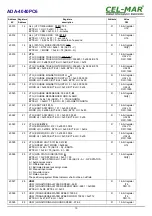
Page 12: ...NGITUDINAL WATER SPEED 998 1 VBW LONGITUDINAL WATER SPEED WORD 9981 0xD903 BYTE HI 0xD9 BYTE LO 0x03 R 16 bit register I16 DW 10 30028 27 VBW TRANSVERSE WATER SPEED 1000 2 VBW TRANSVERSE WATER SPEED W...

Page 13: ...BYTE HI K km h M m s N knots ASCII SPEED UNIT BYTE LO A Data Valid V Data invalid ASCII DATA STATUS R 16 bit register U16 CH 2 30044 43 XDR XDR SENSOR1 VALUE CD AB INT32 CD R 32 bit register I32 DW 10...

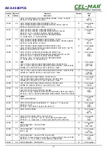
Page 14: ...conds BYTE LO SS 0x00 0 hundredths of a second R 16 bit register U16 40004 3 ZDA UTC DDMM 10 05 2019 BYTE HI DD 0x0A 10 day BYTE LO MM 0x05 05 month R 16 bit register U16 40005 4 ZDA UTC YYY 10 05 201...

Page 15: ...R 16 bit register CH 2 40021 20 VTG KNOTS 0 131 N VTG KNOTS DWORD 131 0x00 00 00 83 WORD LO 0x0083 BYTE HI 0x00 BYTE LO 0x83 R 16 bit register U32 LO DW 1000 40022 21 VTG KNOTS DWORD 131 0x00 00 00 83...

Page 16: ...er U32 LO DW 1000 40036 35 VLW TOTAL CUMULATIVE WATER DISTANCE DWORD 0x05F5 FC88 WORD HI 0x05F5 BYTE HI 0x05 BYTE LO 0xF5 R 16 bit register U32 HI DW 1000 40037 36 VLW DISTANCE SINCE RESET 100007 048...

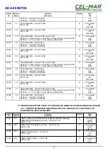
Page 17: ...CHAR1 BYTE LO 3 ASCII ID CHAR2 R 16 bit register U16 CH 2 40056 55 XDR SENSOR4 VALUE CD AB INT32 CD R 32 bit register I32 DW 1000 40057 56 XDR SENSOR4 VALUE CD AB INT32 AB R 32 bit register I32 DW 100...

Page 18: ...L Function code Description 03 0x03 Values readout from MODBUS RTU registers 04 0x04 Values readout from MODBUS RTU registers 8 4 1 FUNCTION 0x03 0x04 READOUT MODBUS REGISTERS VALUE FROM CONVERTER 8 4...

Page 19: ...te 03 04 02 Registry address Hi 1 Byte 00 03 Registry address Lo 1 Byte 00 04 Registry number Hi 1 Byte 00 05 Registry number Lo 1 Byte 01 06 CRC Lo 1 Byte 07 CRC Hi 1 Byte Example Query TALKER ID fro...

Page 20: ...ister value UTC TIME from ZDA sentence Byte no Designation Size Value hex 00 Converter address 1 Byte 11 11 to F7 01 Function code 1 Byte 03 04 02 Error code N Byte 02 03 Dane1 Hi 1 Byte 0E 04 Dane1 L...

Page 21: ...es Baud rates bps 300 600 1200 1800 2400 4800 7200 9600 14400 19200 28800 38400 57600 76800 115200 230400 Data formats Data bits 5 6 7 8 Parity None Parity Odd Number of stop bits 1 2 Transmission lin...

Page 22: ...ge temperature 40 70 C Casing Dimensions 53 x 90 x 62 mm Material PC ABS Degree of casing protection IP40 Degree of terminal protection IP20 Weight 0 10 kg According to standard DIN EN50022 DIN EN4388...

Page 23: ...23 ADA 4040PC6...
Page 24: ...data transmission converters with interface RS232 RS485 RS422 USB Current Loop Fibre Optic Converters and Ethernet or Wi Fi Please contact us to tell how you like our products and how we can satisfy...

Reviews: