background image

3.3.3. LINE TERMINATION Rt

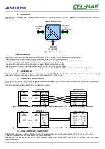
The application of Line Termination (terminator) Rt = 120 ohms will reduce electrical reflection in data line at high baud rate. It is not 

needed below 9600Bd. Should be used the Line Termination resistor if the distance is over 1000m @ 9600Bd or 700m @ 19200Bd, 

and if the disturbance in transmission will appear. 
Example connection of Rt are shown on Fig. 6 & 7. Four Rt=120 

, 5%, 0,25W are delivered with the converters.

3.4.  POWER SUPPLY CONNECTION

To connect power supply to the converter, should have DC power supplies (regulated) output voltage from 10 V= to 30V=, min.

nominal power 2W, e.g. HDR-15-24. Power cable from DC power supplies to device can not be longer than 3m. Should connect

positive (+) end of DC power supplies to V+ device terminal and negative (-) end to V- on terminal block. ADA-4040PC6 has protection

against power supply reverse connection.

4. ACTIVATION

The converter can be power on after properly connection according to section above.

If   after   connection   power   supply   on   front   panel   will   not   light   green   led   PWR,   check   correctness   of   power   supply   connecting

(polarization). When data is present the LEDs Tx and Rx should blink

ATTENTION!

AT BAUD RATE ABOVE 38.4 KBPS THE LED'S TX, RX WILL LIGHT WEAKLY DURING DATA TRANSMISSION

4.1. DESCRIPTION OF SIGNALLING LEDS 

LED

Description

PWR

Signalling of Power Supply

RX

Signalling of data receiving through ADA-4040PC6 from RTU RS485/RS422 port.

TX

Signalling of data transmitting from ADA-4040PC6 through RTU RS485/RS422 port.

Yellow LED by 

SW1

Not light – signalling of normal operating mode (RUN)
Blinking at frequency 1 Hz – signalling of configuration mode or data flow of software to the converter.
Blinking at frequency 2 Hz – signalling of factory default mode
Lit continuously – signalling of emergency firmware update

4.2. TROUBLESHOOTING

Problem

Solutions

PWR LED is not light

Check polarization and parameters of connected power supply.

Rx LED lights 

continuously

RS485(4W)   /422   network.   Wrong   polarization   on   terminals:  Rx+,   Rx-   RTU   port;  change

polarization.

No transmission

Tx LED is blinking

RS485(4W) / RS422 network. Check correctness of connection to terminals Tx, Rx; according to

point 3 and the converter configuration.

5. CONFIGURATION

5.1. OPERATION MODE

ADA-4040PC6 converter can operates in a few modes:

RUN,

configuration,

factory default,

emergency firmware update mode,

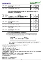
Those modes can be set by use SW1 located by screw terminal block NMEA0183 port. To set the switch section, should remove 

terminal cover marked as SW1 and make the appropriate settings by the use a small, flat screwdriver. Figure 1 present the location of 

two-position SW1 micro-switch. 

All available adjusting the SW1 switch are shown in table below.

Converter operation modes

SW1- 1

SW1- 2

Mode

OFF

OFF

Run

ON

OFF

Configuration

OFF

ON

Factory default

ON

ON

Emergency firmware update

5.2. CONFIGURATION BY USING ADACONFIG

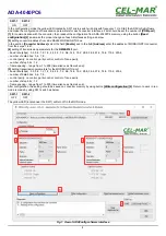
The configuration of ADA-4040PC6 converter can be made by the use of 

ADAConfig

 Software - selling with converter. To make the 

configuration, connect converter to computer (see pt. 3.2) and power supply. If after power, on the front panel is not lit green LED 

PWR, check the power connection (polarity). If the PWR LED lights, set the section of SW1 switch to configuration mode as in table 

below.

7

ADA-4040PC6

Summary of Contents for ADA-4040PC6

Page 1: ...User manual ADA 4040PC6 NMEA0183 to MODBUS RTU Protocol Converter 1 ADA 4040PC6 Copyright 2001 2022 CEL MAR sp j io_ada 4040pc6_v1 05_en...

Page 2: ...IMPLEMENTATION OF MODBUS RTU PROTOCOL 10 8 1 MODBUS REGISTERS TABLE OF STANDARD NMEA0183 SENTENCE 10 8 1 1 CONVERTER MODBUS REGISTERS TABLE IN READOUT BY FUNCTION 04 3X REFERENCES INPUT REGISTERS 10...

Page 3: ...ply network is only after disconnecting the power supply circuit voltage Do not carry out the assembly or disassembly of the device if it is enabled This may result to short circuit and damage the dev...

Page 4: ...bles connected to screw terminals The converter use RX RX TX A TX B lines for functioning It is possible to connect 32 devises to RS485 RS422 network constructed on base of ADA 4040PC6 working at the...

Page 5: ...sound 3 2 COMPUTER CONNECTION To connect ADA 4040PC6 to computer is needed additional converter e g ADA I9141 USB to RS485 RS422 converter connected to NMEA 5 pin connector port of the converter Typic...

Page 6: ...re bus and FURUNO GP 150 NMEA0183 6 ADA 4040PC6 RS485 RS422 connector RS485 4W BUS 19200Bd 8 N 1 MODBUS RTU MASTER MODBUS RTU DEVICE SLAVE 2 MODBUS RTU SLAVE 1 MODBUS RTU GND Rt Rt Rx Rx Tx A Tx B RS4...

Page 7: ...lling of normal operating mode RUN Blinking at frequency 1 Hz signalling of configuration mode or data flow of software to the converter Blinking at frequency 2 Hz signalling of factory default mode L...

Page 8: ...3 port baud rate kbps 0 3 0 6 1 2 1 8 2 4 4 8 7 2 9 6 14 4 19 2 28 8 38 4 57 6 76 8 115 2 230 4 number of data bites 5 6 7 8 control parity no control parity control control of none parity number of s...

Page 9: ...after proper changing confirmed by correct message Fig 8 Selection of firmware file During loading software the yellow LED located beside SW1 micro switch will blink showing data flow to the converte...

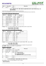
Page 10: ...arator of NMEA0183 port from MODBUS RTU port ADA 4040PC6 reads data from NMEA0183 device and properly processed write them to registers of MODBUS RTU protocol described in pt IMPLEMENTATION OF MODBUS...

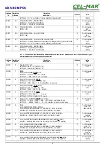
Page 11: ...2 30010 9 GLL LONGITUDE 00636 58680 W GLL LONGITUDE DWORD 63658680 0x03 CB 5A B8 WORD LO 0x5AB8 BYTE HI 0x5A BYTE LO 0xB8 R 16 bit register U32 LO DW 10000 30011 10 GLL LONGITUDE DWORD 63658680 0x03...

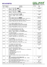
Page 12: ...NGITUDINAL WATER SPEED 998 1 VBW LONGITUDINAL WATER SPEED WORD 9981 0xD903 BYTE HI 0xD9 BYTE LO 0x03 R 16 bit register I16 DW 10 30028 27 VBW TRANSVERSE WATER SPEED 1000 2 VBW TRANSVERSE WATER SPEED W...

Page 13: ...BYTE HI K km h M m s N knots ASCII SPEED UNIT BYTE LO A Data Valid V Data invalid ASCII DATA STATUS R 16 bit register U16 CH 2 30044 43 XDR XDR SENSOR1 VALUE CD AB INT32 CD R 32 bit register I32 DW 10...

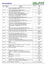
Page 14: ...conds BYTE LO SS 0x00 0 hundredths of a second R 16 bit register U16 40004 3 ZDA UTC DDMM 10 05 2019 BYTE HI DD 0x0A 10 day BYTE LO MM 0x05 05 month R 16 bit register U16 40005 4 ZDA UTC YYY 10 05 201...

Page 15: ...R 16 bit register CH 2 40021 20 VTG KNOTS 0 131 N VTG KNOTS DWORD 131 0x00 00 00 83 WORD LO 0x0083 BYTE HI 0x00 BYTE LO 0x83 R 16 bit register U32 LO DW 1000 40022 21 VTG KNOTS DWORD 131 0x00 00 00 83...

Page 16: ...er U32 LO DW 1000 40036 35 VLW TOTAL CUMULATIVE WATER DISTANCE DWORD 0x05F5 FC88 WORD HI 0x05F5 BYTE HI 0x05 BYTE LO 0xF5 R 16 bit register U32 HI DW 1000 40037 36 VLW DISTANCE SINCE RESET 100007 048...

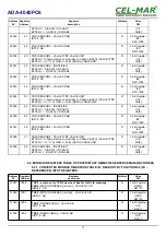
Page 17: ...CHAR1 BYTE LO 3 ASCII ID CHAR2 R 16 bit register U16 CH 2 40056 55 XDR SENSOR4 VALUE CD AB INT32 CD R 32 bit register I32 DW 1000 40057 56 XDR SENSOR4 VALUE CD AB INT32 AB R 32 bit register I32 DW 100...

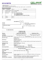
Page 18: ...L Function code Description 03 0x03 Values readout from MODBUS RTU registers 04 0x04 Values readout from MODBUS RTU registers 8 4 1 FUNCTION 0x03 0x04 READOUT MODBUS REGISTERS VALUE FROM CONVERTER 8 4...

Page 19: ...te 03 04 02 Registry address Hi 1 Byte 00 03 Registry address Lo 1 Byte 00 04 Registry number Hi 1 Byte 00 05 Registry number Lo 1 Byte 01 06 CRC Lo 1 Byte 07 CRC Hi 1 Byte Example Query TALKER ID fro...

Page 20: ...ister value UTC TIME from ZDA sentence Byte no Designation Size Value hex 00 Converter address 1 Byte 11 11 to F7 01 Function code 1 Byte 03 04 02 Error code N Byte 02 03 Dane1 Hi 1 Byte 0E 04 Dane1 L...

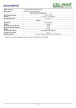
Page 21: ...es Baud rates bps 300 600 1200 1800 2400 4800 7200 9600 14400 19200 28800 38400 57600 76800 115200 230400 Data formats Data bits 5 6 7 8 Parity None Parity Odd Number of stop bits 1 2 Transmission lin...

Page 22: ...ge temperature 40 70 C Casing Dimensions 53 x 90 x 62 mm Material PC ABS Degree of casing protection IP40 Degree of terminal protection IP20 Weight 0 10 kg According to standard DIN EN50022 DIN EN4388...

Page 23: ...23 ADA 4040PC6...
Page 24: ...data transmission converters with interface RS232 RS485 RS422 USB Current Loop Fibre Optic Converters and Ethernet or Wi Fi Please contact us to tell how you like our products and how we can satisfy...

Reviews: