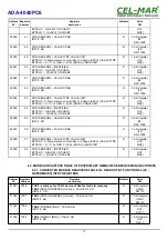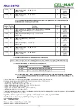
SW1-1
SW1-2
ON
OFF
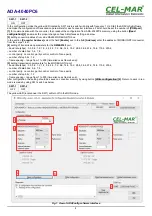
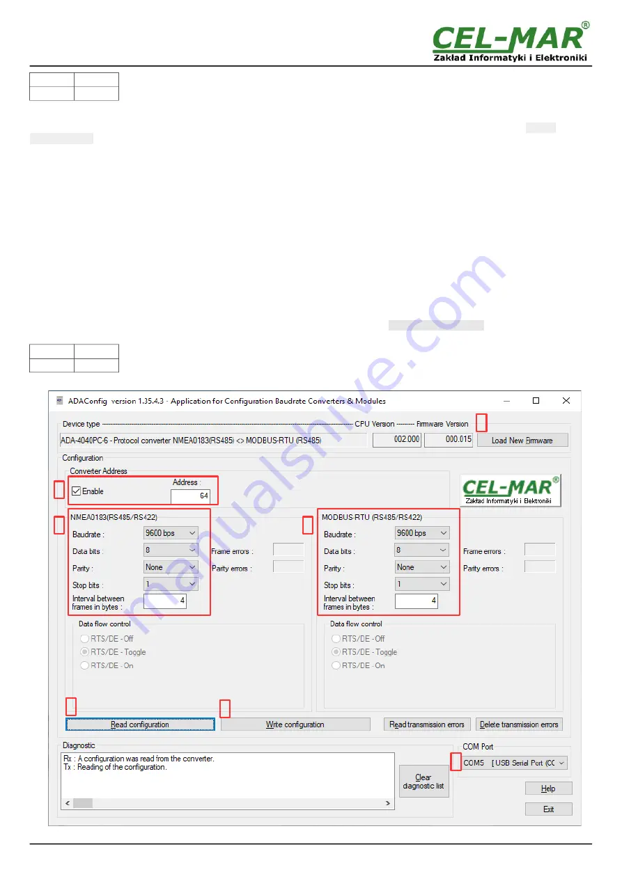
In the configuration mode the yellow LED located by SW1 micro-switch will blink with frequency 1 Hz. Start the ADAConfig Software
and make the configuration of transmission parameters for each converter interfaces. First should be set the number of
[COM port]
[1]
for communication with the converter, then readout the configuration from ADA-4040PC6 memory, using the button
[Read
configuration]
[2]
and make the proper changes of each interfaces setting, as below.
[3]
setting converter address from side RS485 MODBUS-RTU bus,
In the section
[Converter Address]
select the field
[Enable]
and in the field
[Address]
enter the address of MODBUS-RTU converter,
from the scope 1-247.
[4]
setting of transmission parameters for the
NMEA0183
port,
– baud rate (kbps) : 0.3, 0.6, 1.2, 1.8, 2.4, 4.8, 7.2, 9.6, 14.4, 19.2, 28.8, 38.4, 57.6, 76.8, 115.2, 230.4,
– number of data bites: 5, 6, 7, 8,
– control parity: no control, parity control, control of none parity,
– number of stop bits : 1, 2,
– frame spacing – range from 1 to 255 (time silence as frame's end),
[5]
setting transmission parameters for the MODBUS-RTU port:
– baud rate (kbps) : 0.3, 0.6, 1.2, 1.8, 2.4, 4.8, 7.2, 9.6, 14.4, 19.2, 28.8, 38.4, 57.6, 76.8, 115.2, 230.4,
– number of data bites: 5, 6, 7, 8,
– control parity: no control, parity control, control of none parity,
– number of stop bits : 1, 2,
– frame spacing – range from 1 to 255 (time silence as frame's end),
After configuration, the setting should be saved on converter memory by using button
[Write configuration]
[6]
. Return to work in run
mode is made by using SW1 switch as below.
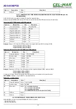
SW1-1
SW1-2
OFF
OFF
The yellow LED (located near the SW1) will turn off in the RUN mode.
Fig.7. View of ADAConfig software interface
8
ADA-4040PC6
1
3
2
4
5
6
7
Summary of Contents for ADA-4040PC6
Page 23: ...23 ADA 4040PC6...

