2.4. CURRENT LOOP RECEIVER
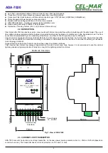
In ADA-7020 converter has been used passive RX receiver consisting of optoisolator (optical coupler) and protective elements. The
receiver circuit has RX+, RX- terminals as well as the terminal marked as RX-*. In the circuit with RX-* terminal has been used
additional resistor 1k, to reduce power in the case of small impedance.
The RX red LED on front panel of the converter is a signalization of NO current flow through optocoupler. This LED is ON when it is:
- not connect transmitter to receiver,
- wrong connection of transmitter to receiver,
- broken connection of transmitter to receiver.
2.5. ISOLATION
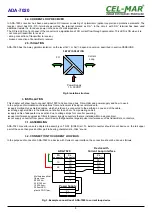
ADA-7020 has the 3-way galvanic isolation, on the level 1kV= or 3kV=, depend on version, described in section VERSIONS.
Fig.2. Isolation structure
3. INSTALLATION
This chapter will show how to connect ADA-7020 to Current Loop bus, Fibre-Optic and power supply and how to use it.
In the purpose of minimization of disruptions from environment is being recommended to:
●
apply multipair type shielded cables, which shield can be connected to the earthing on one end of the cable,
●
arrange signal cables in the distance not shorter than 25 cm from powering cables,
●
apply cable of adequate cross-section due to voltage drops for converter powering,
●
use Interference suppression filters for power supply converters that are installed within a single object.
●
not supply converter from power circuit device that generates large impulse interference such as transmitters, contactors,
3.1. ASSEMBLING
ADA-7020 converter case is adapted to assembly on TS-35 (DIN35) rail. To install converter should mount device on the rail upper
part of the case then press bottom part to hearing characteristic „Click” sound.
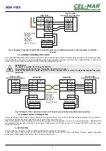
3.2. CONNECTION TO CURRENT LOOP BUS
In the purpose of connection ADA-7020 to a device with Current Loop interface, the connection should be done as follows.
Fig. 3. Example connection of ADA-7020 to current loop device
5
ADA-7020
Device with
Current Loop interface
TX+
TX-
RX+
RX-
FO
connector
RX+
RX-
TX+
TX-
V +
V -
V -
V +
CL
connector
Power Supply
ADA-7020
Multimode optical
fibers type:
50/125um,
62,5/125 um,
100/140um,
200umHCS,
plastic POF/1mm,
TX
RX
RX+*
CL
connector
Power Supply
10 - 30VDC
FO
Current
Loop
3-WAY ISOLATION

