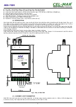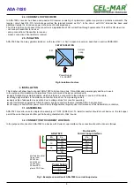
Fig. 4. Example connection of ADA-7020 to current loop device via additional resistor in the transmitter circuit (RX+*
terminal)
3.3. CONNECTION FIBRE-OPTIC BUS
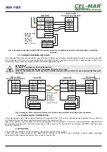
The multimode Fibre-Optic with connectors type: ST®, SC or SMA, connect into their corresponding converter's connectors type: ST®,
SC or SMA like on the Fig. 6. Connecting the fiber optic cables should be cautious and careful not to damage them or dirty. If it is
necessary to lay the cable at an angle, must be created the appropriate bends.
ATTENTION!!!
The device is equipped in the laser transmitter.
The radiation emitted by the laser transmitter is harmful to the eyes!
Under no circumstances should never look to at the uncovered slot, to which it is not connected the fiber optic
connector.
Fig. 5. Example of the connection devices with Current Loop interface using fiber optic converters.
3.4. POWER SUPPLY CONNECTION
The power supply to ADA-7020 converter should be DC (regulated) from 10 V= to 30V=. Nominal power is typically 2W, e.g. HDR-15-
24. Power cable from DC power supplies to device must not be longer than 3m.
Observe the polarity, connect positive (+) of DC power supplies to V+ and negative (-) end to V- screw terminal block. ADA-7020 has
the protection from opposite connection power supply. If after power, on the front panel is not lit green LED PWR, check the power
connection (polarity).
4. ACTIVATION
The converter can be power on after properly connection according to section above.
If after connection power supply on front panel will not light green led PWR, check correctness of power supply connecting
(polarization). When data is present the LEDs Tx and Rx should blink.
6
ADA-7020
TX+
TX-
RX+
RX-
RX+
RX-
TX+
TX-
V -
V +
ADA-7020
TX
RX
RX+*
Multimode optical
fibers type:
50/125um,
62,5/125 um,
100/140um,
200umHCS,
plastic POF/1mm,
FO
connector
CL
connector
CL
connector
Device with
Current Loop interface
V +
V -
Power Supply
TX+
TX-
RX+
RX-
TX
RX
RX+
RX-
TX+
TX-
ADA-7020
RX+
RX-
TX+
TX-
ADA-7020
TX+
TX-
RX+
RX-
TX
RX
FO
connector
V +
V -
V -
V +
CL
connector
Power Supply
CL
connector
Device with
Current Loop interface
CL
connector
Device with
Current Loop interface
CL
connector
FO
connector
V +
V -
V -
V +
Power Supply
Multimode optical
fibers type:
50/125um,
62,5/125 um,
100/140um,
200umHCS,
plastic POF/1mm,

