background image

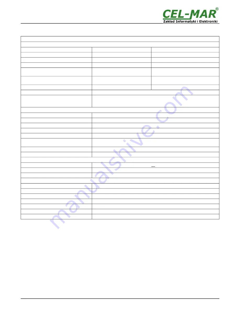
10. SPECIFICATION

TECHNICAL DATA

Transmission Parameters

Interface

USB

1-WIRE

Connector

B-type female 

Screw terminal block, max. wire Ø2,5mm²

Line length

up to 5 m

up to 300 m – for DS1820 sensors

Maximum number of connected devices

1

up to 100 of DS18B20 circuits

Transmission line

USB Aw-Bw cable

Twisted cable 1-pair, 2- pair UTP Cat.5e, 

shield inside large interferences STP Cat. 5e.

Standards

 9.6, 19.2, 57.6, 115.2 [kbit/sec]

standard: 0 do 16,3 kbps,

overdrive: 0 do 142 kbps,

Maximum baud rate

USB1.1, USB2.0

1-WIRE

Transmission type 

1-WIRE - half duplex (transmitting and receiving on the same wire)

Optical Signalization

PWD – green LED power supply,

RX – red LED received data via 1-WIRE interface,

TX – yellow LED transmitted data via 1-WIRE interface.

Electrical Parameters

Power requirements

from USB of Computer

Power Cable

USB cable

Power

<1W

Galvanic Isolation

1kV DC or 3kV DC – between USB and 1-WIRE interfaces

Optoisolation

~3kV - between  signal line USB and 1-WIRE interfaces

Electromagnetic compatibility

Resistance to disruptions according to the standard PN-EN 55024.

Emission of disruptions according to the standard PN-EN 55022.

Safety requiring

According to the PN-EN60950 norm.

Environment

Commercial and light industrial.

Environmental Parameters

Operating temperature

0 ÷ +23 ÷ +50°C

Humidity

5 ÷ 95% - non-condensing

Storage temperature

-20 ÷ +60 °C

Casing

Dimensions (W x D x H)

65mm x 50mm x 27mm

Material

ABS

Degree of casing protection

IP20

Weight

< 0,10 kg

Implementation of Standard

Not applicable

Location during work

Free

Mounting method

Not applicable

15

ADA-I911W

Summary of Contents for ADA-I911W

Page 1: ...User manual ADA I911W USB to 1 WIRE converter 1 io_ada i911w_v en 1 01 ADA I911W Copyright 2001 2017 CEL MAR sp j...

Page 2: ...WIRE SENSORS CONNECTION 5 4 3 POWER SUPPLY 6 5 DRIVERS INSTALLATION IN SYSTEM WINDOWS 6 5 1 EXAMPLE DRIVER INSTALLATION IN WINDOWS 7 SYSTEM 6 6 DRIVER UNINSTALLATION 12 6 1 DRIVER UNINSTALLATION IN W...

Page 3: ...pt open or make holes in casings of the device Do not immerse device in water or no other liquid Do not put the fire opened on device sources candles an oil lamps and the like Complete disable from th...

Page 4: ...heating a remote control and monitoring of alarm systems fire extinguishers etc One of the fastest growing markets today is the market of alarm systems in which MicroLAN is used for connection the sen...

Page 5: ...nment on 1 WIRE bus it is recommended to use multipair type shielded cables which shield can be connected to the earthing on one end of the cable lay signal cables at a distance of not less than 25 cm...

Page 6: ...tion wizard will be installed the Drivers and Uninstaller for the Windows systems 98 ME 2000 XP 2003 Vista Win7 2008 Win8 d connect the convert to USB port of computer and follow the steps of installa...

Page 7: ...Press Next Select STANDARD Drivers and press Next 7 ADA I911W...

Page 8: ...Press Install Press Next will be installed Drivers for USB Bus 8 ADA I911W...

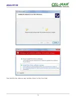
Page 9: ...Press Install this driver software anyway Installation of drivers for USB Bus will start 9 ADA I911W...

Page 10: ...Press Install this driver software anyway Installation of drivers for Virtual Port will start 10 ADA I911W...

Page 11: ...Press Finish Press Finish The driver for ADA I911W have been installed This can be checked in Uninstall or change a program 11 ADA I911W...

Page 12: ...ring installation was selected driver for Standard baud rates it is possible to use 9600 bps standard 19200 bps 57600 bps 115200 bps supported by the DS9097U adapter Selecting other baud rates will re...

Page 13: ...g press Change Remove driver converter of USB Bus will be uninstalled h after uninstallation reboot the computer 6 2 1 EXAMPLE DRIVER UNINSTALLATION IN WINDOWS 7 SYSTEMS Driver uninstallation in Windo...

Page 14: ...nstaller d from CDMUninstaller folder run the application uninstall bat e after finishing reboot the computer 7 USING After proper connection according to section above the converter can be used If co...

Page 15: ...terface TX yellow LED transmitted data via 1 WIRE interface Electrical Parameters Power requirements from USB of Computer Power Cable USB cable Power 1W Galvanic Isolation 1kV DC or 3kV DC between USB...

Page 16: ...ta transmission converters with interface RS232 RS485 RS422 USB Current Loop Fibre Optic Converters and Ethernet or Wi Fi Please contact us to tell how you like our products and how we can satisfy you...

Reviews: