2.7. ISOLATION
ADA-I911W converter has 1kV= or 3kV galvanic isolation, depending on the version of device, described in pt.
VERSIONS.
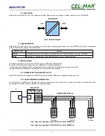
Fig. 2. Isolation diagram
3. CONFIGURATION
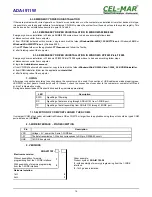
ADA-I911W converter can be set for operating in normal mode or programming mode by the use of MODE switch (fig.1). Description
of the switch modes is shown in the table below.
MODE switch
Function
NORM
Operating in normal mode, allows to read data from the 1-WIRE interface circuits eg. DS18B20
PROG
Operating in programming mode of EPROM memory with 1-WIRE interface
4. INSTALLATION
This chapter will show how to connect ADA-I911W to 1-WIRE and USB interfaces.
To reduce disturbance from environment on 1-WIRE bus, it is recommended to:
- use multipair type shielded cables, which shield can be connected to the earthing on one end of the cable,
- lay signal cables at a distance of not less than 25 cm away from power cables,,
4.1. CONNECTION TO USB PORT OF PC
ADA-I911W converter is connected to USB of PC by the use USB Aw-Bw cable, supplied with the converter.
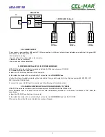
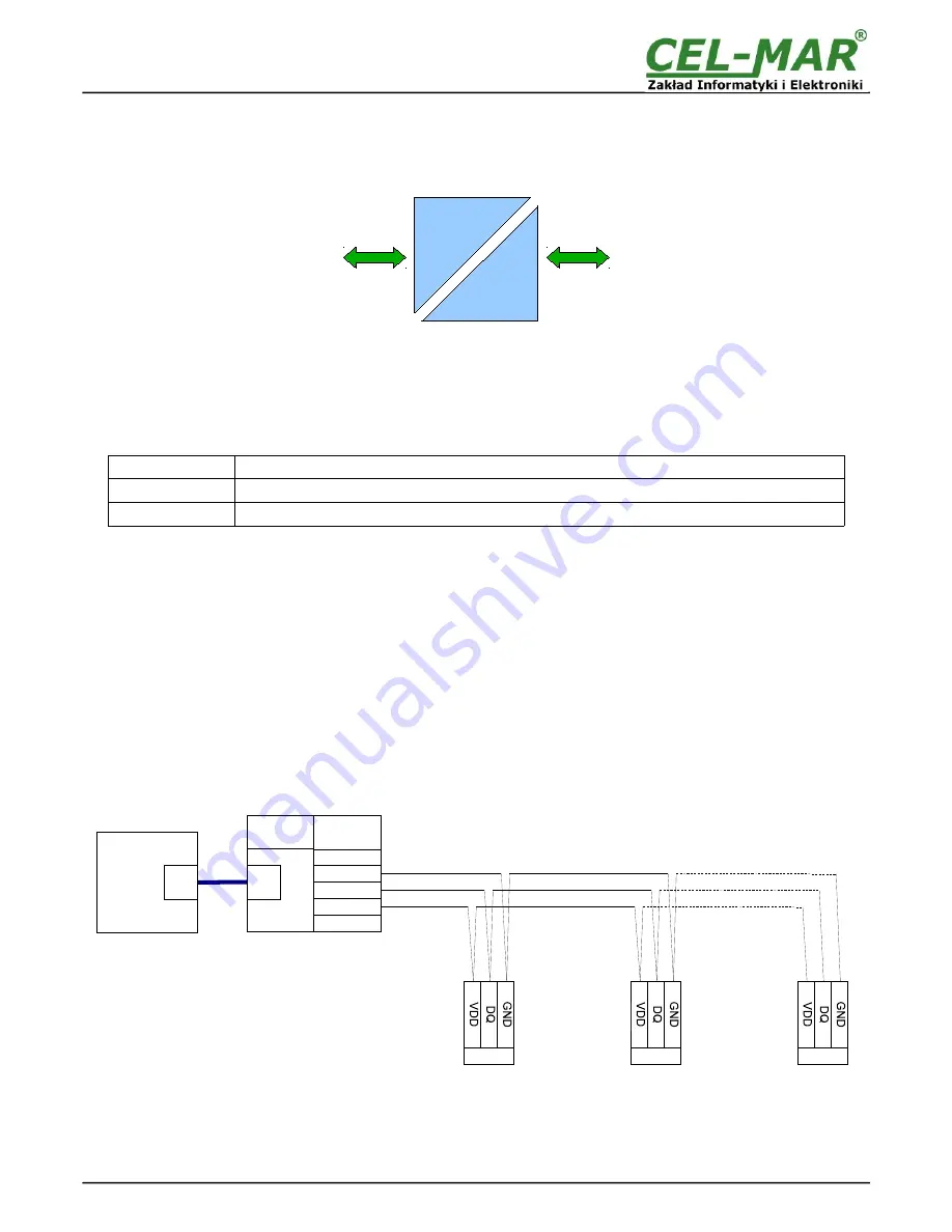
4.2. 1-WIRE SENSORS CONNECTION
For connection of 1-WIRE bus to ADA-I911W converter, should have flat screwdriver for connection of wires to terminal block. The
connections of 1-WIRE sensors to ADA-I911W are shown below.
Fig 4. Sensors connection to ADA-I911W by 3-wire 1-WIRE bus.
Fig 5. Sensors connection to ADA-I911W by 2-wire 1-WIRE bus.
5
1-WIRE
USB
ISOLATION
ADA-I911W
1-WIRE
connector
USB
connector
1-WIRE (3W) Network
ADA-I911W
Sensor
DS18B20
VDD
GND
1-W
Sensor
DS18B20
Sensor
DS18B20
USB
B
PC
USB
A

