●
USB interface connection via cable with USB-type A connector,
●
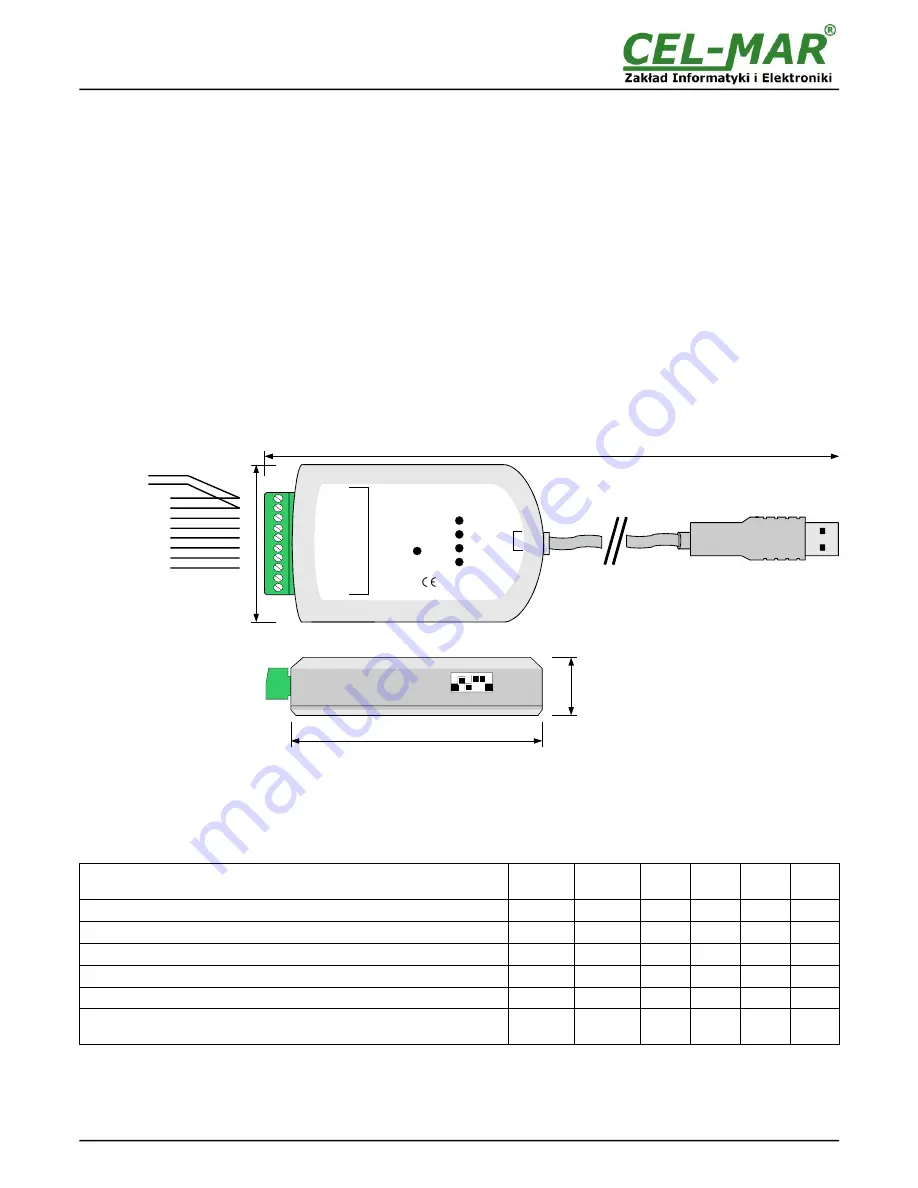
Casing dimensions (W x D x H) 91mm x 21mm x 57mm,
2.2. DESCRIPTION
ADA-I9140 converts USB to RS-485/RS-422 standard without interference of data format and it is automatically detected by PC
system (Windows/ Linux/ MAC OS) after connecting to USB socked (Plug&Play device). Converter transmits
RX
,
TX signals and two
additional RTS, CTS or DTR, DSR set by SW2 microswitch.
For communication with other devices ADA-I9140 uses data transmission line like:
●
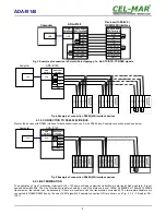
RX+,RX-,TX+/DATA+,TX-/DATA-
(RS-485/422),
●
CTS+/DSR+,CTS-/DSR-,RTS+/DTR+,RTS-/DTR-
(RS-422)
There is also the possibilities of looping the
DTR with DSR signal or RTS with CTS signals
.
This converter doesn't required external power supply (it is powered from USB bus) and it uses asynchronous baud rate up to 921,3
kbps (drivers for STANDARD baud rate) / 1500000 bps (drivers for PROFIBUS baud rate). The converter has implemented
overvoltage protection RS485/RS422 interface, 2,7kV= optoisolation in signal channel between USB and RS-485/422 interface and
1kV= or 3kV= galvanic isolation. USB cable with A-type plug enables simple connection to a computer and on other side simple
connection the RS485/422 Bus provide plug-in screw terminal block.
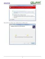
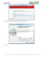
Together with the ADA-I9140 we provide the drivers, which after installation, create in operating system additional COM port on the
next free number e.g. COM3. It can be use as standard COM port but it isn't hardware port but virtual, create in Windows system. This
is the reason why some applications running in DOS and use this port, can operate improperly.
3. CONFIGURATION
For configuration ADA-I9140 are used two dipswitches SW1 and SW2.
Fig. 1. ADA-I9140 view
3.1. ADDITIONAL SIGNAL CONFIGURATION
For configuration of additional signals is used 6-position dipswitch SW2. A table below shows typical configuration of additional signals
RTS, CTS, DTR, DSR. Other configuration possibilities should be agreed with Technical Support – +48 41 362-12-46.
The 6-position dipswitch SW2 is located on one side of the converter.
Table 1. Setting of SW2 dipswitch for 2-x version of ADA-I9140
Function
SW2-1
DTR-DSR
SW2-2
RTS-CTS
SW2-3
DTR
SW2-4
DSR
SW2-5
RTS
SW2-6
CTS
Tx, Rx signals conversion (default setting)
OFF
OFF
OFF
OFF
OFF
OFF
Tx, Rx, RTS, CTS signals conversion
OFF
OFF
OFF
OFF
ON
ON
Tx, Rx, DTR, DSR signals conversion
OFF
OFF
ON
ON
OFF
OFF
Tx, Rx, RTS, CTS signals conversion, DTR looped with DSR
ON
OFF
OFF
OFF
ON
ON
Tx, Rx, DTR, DSR signals conversion, RTS looped with CTS
OFF
ON
ON
ON
OFF
OFF
Tx, Rx signals conversion, RTS looped with CTS and DTR looped with
DSR
ON
ON
OFF
OFF
OFF
OFF
4
ADA-I9140
ADA-I9140
PWR
U
S
B
Tx-/DATA-
Tx+/DATA+
Rx-
Rx+
RTS-/DTR-
RTS+/DTR+
CTS-/DSR-
CTS+/DSR+
GND
100R
R
S
-4
85
/R
S
-4
22
(SW1)
USB to RS-485/422 ISOLATED CONVERTER
(SW2)
RTS/DTR
CTS/DSR
Tx
Rx
5
7m
m
RS-485
2-WIRE
RS-485 4-WIRE
or
RS-422
ADDITIONAL
SIGNALS IN
RS422 STANDARD
≈ 960 mm
21
m
m
91mm

