6. ACTIVATION
Converter can be powered after proper connection according to steps above.
If connection was made properly green LED PWR on front panel of converter should light, if not check polarization of power
connection. When data is present the LEDs Tx and Rx should blinking.
6.1. SIGNALLING LEDS
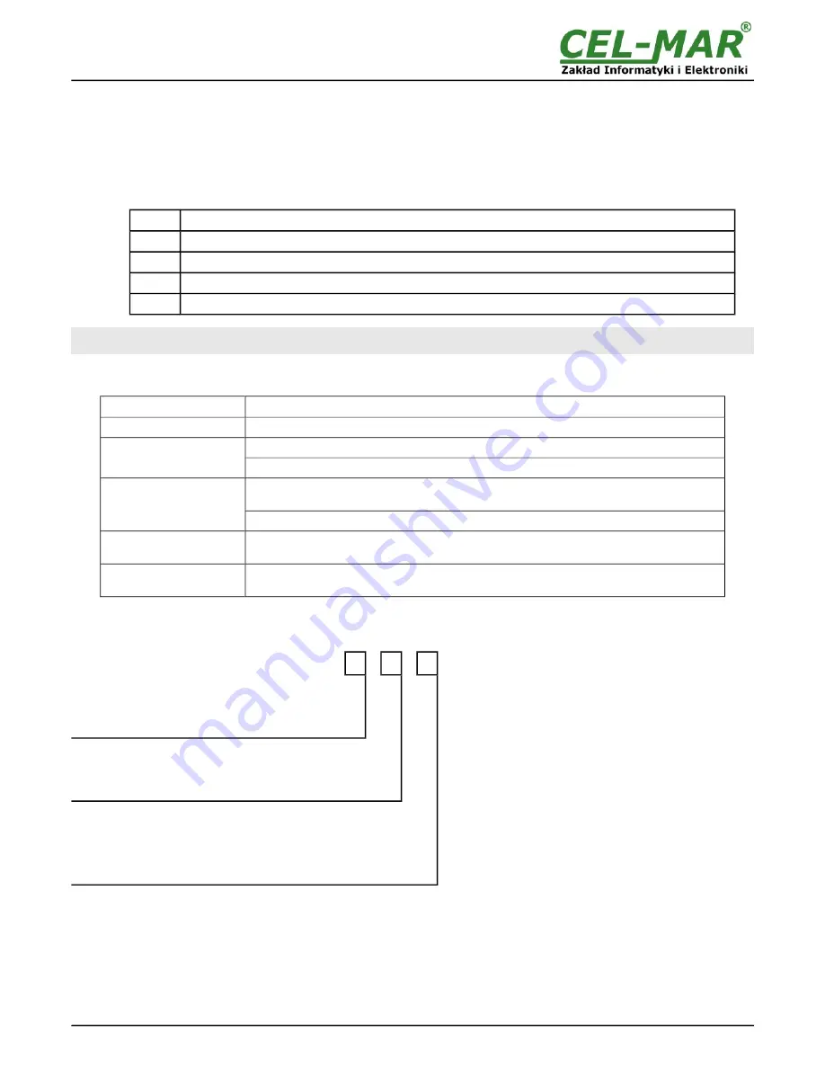
LED
Description
PWR
Signalling of Power Supply
RX
Signalling of data receiving from RS485/RS422 port of ADA-M140
TX
Signalling of data transmitting from converter via RS485/RS422 port of ADA-M140
DCD
Signalling of correctness connection of converters by the use of M-1 buses.
ATTENTION!
AT BAUD RATE ABOVE 38.4 KBPS THE LED'S TX, RX WILL LIGHT WEAKLY DURING DATA TRANSMISSION
6.2. TROUBLESHOOTING
Problem
Solutions
PWR led not light
Check polarization and parameters of connected power supply.
Rx LED lights
continuously
RS485(4W) /RS422 bus. Wrong polarization on Rx+, Rx- terminals. Change polarization.
RS485(2W) bus. Wrong polarization on Tx+/A, Tx-/B terminals. Change polarization.
No transmission,
Tx led blinking.
RS485(4W) /RS422 bus. Check the correctness of connection to Tx, Rx terminals according
to chapter 3.
RS485(2W) bus. Check the correctness of configuration setting according to chapter 4.
DCD led not light
Interruption or incorrect connected of M-1 bus. Check the correctness of connection. Check
the continuity of M-1 bus.
DCD led not light,
Tx led lights.
M-1 bus. Wrong polarization on Rx+, Rx- terminals of M-1 bus. Change polarization.
7. VERSIONS
ADA-M140 -
-
-
Order example:
Product Symbol:
ADA-M140-1-2-3
1
– basic electronics version,
2
– 1kV=, 2-way galvanic isolation,
3
– cover without inlets, plug-in screw terminal block.
Electronics version:
Basic
1
Special
2
Galvanic isolation:
1kV=, 2-way
2
1kV=, 3-way
23
Terminals & Terminals Cover:
Cover without inlets, screw terminal block
1
Cover with inlets, screw terminal block
2
Cover without inlets, plug-in screw terminal block
3
10
ADA-M140

