background image

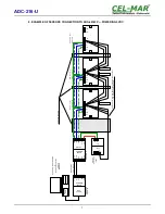
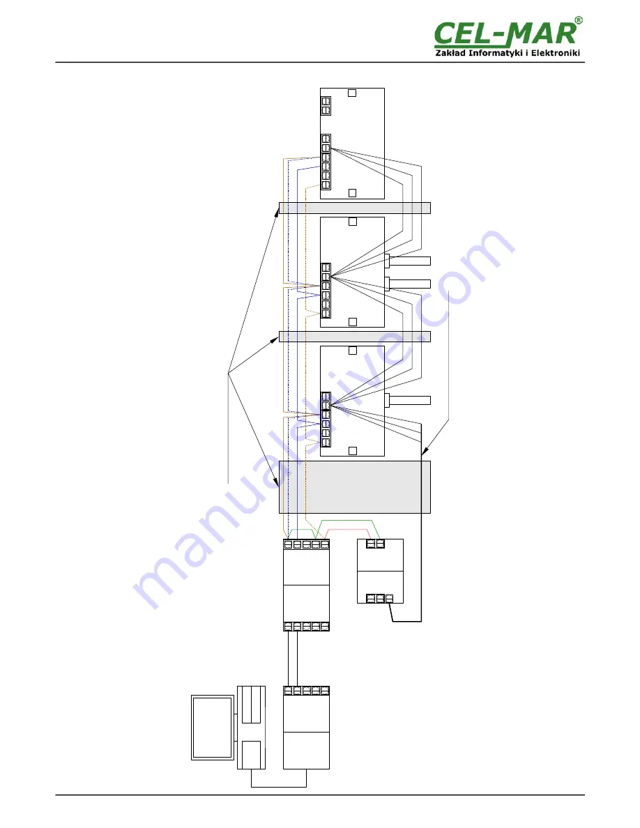
9. EXAMPLE OF SENSORS CONNECTION TO ADA-401WP — POWERING 12VDC

8

ADC-216-U

T

x-

/B

T

x+

/A

R

x-

1-W

IR

E

RS4

85

MO

DB

US

A

D

A

-I

10

40

A

D

A

I9

14

0

G

N

D

R

x+

1-

W

V

D

D

R

S

23

2

U

S

B

RS4

85

MO

DB

US

P

E


G

N

D

T

x-

/B

T

x+

/A

R

x-

G

N

D

R

x+

RS

23

2

US

B

V

ss

V

ss

+


230

V~

V

N


V

+


12V

A

D

A

-4

01

W

P

R

L

NC

GN

D

NC

VD

D

+12

V

1-W

NC

GN

D

NC

VD

D

+12

V

1-W

R

L

VA

D

GN

D

GN

D

VD

D

+12

V

1-W

R

L

NC

NC

A

D

C

-2

16

-U

 (

E

L

)

E

N

D

 L

E

F

T

st

ab

ili

ze

d


p

ow

er

 s

up

p

ly

12

 V

D

C

D

E

S

-2

16

-T

 (

F

)

S

tr

a

ig

ht

-t

hr

o

ug

h

D

E

S

-2

16

-T

-H

 (

F

)

S

tr

a

ig

ht

-t

hr

o

ug

h

R

S

48

5(

2W

)

up

 to

 1

20

0m

C

ab

le

 U

T

P

 4

x2

x0

,5

C

om

pu

te

w

ith

 F

re

e

S

C

A

D

A

o

r

P

LC

 w

ith

 s

up

po

rt

 th

e


pr

ot

oc

ol

M

O

D

B

U

S

U

nu

se

w

ire

of

 tw

is

te

p

ai

co

nn

ec

t t

og

e

th

e

a

nd

 c

on

n

ec

th

e

le

ct

ri

ca

l i

n

st

a

lla

tio

P

E

Summary of Contents for ADC-216-U

Page 1: ...User manual ADC 216 U Analog signal 0 10V DC to 1 WIRE Converter 1 io_adc 216 u_en_v1 00 ADC 216 U Copyright 2001 2016 CEL MAR sp j ...

Page 2: ...CONSERVATION 3 1 6 PACK CONTENTS 3 2 APPLICATION 3 3 FUNCTIONING WITH OTHER 1 WIRE DEVICES 4 4 CONVERTER VIEW 4 5 CONNECTION OF 1 WIRE BUS 5 6 CONFIGURATION OF POWER SUPPLY 5 7 CONNECTION OF 0 10VDC 6 8 EXAMPLE OF SENSORS CONNECTION TO ADA 401WP POWERING 5VDC 7 9 EXAMPLE OF SENSORS CONNECTION TO ADA 401WP POWERING 12VDC 8 10 VERSIONS 9 11 PARAMETERS 9 2 ADC 216 U ...

Page 3: ...o not adapt open or make holes in casings of the device Do not immerse device in water or no other liquid Do not put the fire opened on device sources candles an oil lamps and the like The device can not be used in applications that determine human life and health eg Medical 1 3 CE LABEL CE symbol on organizing the company CEL MAR a conformity of the device to the directive of the electromagnetic ...

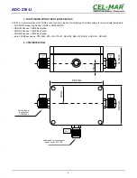
Page 4: ...IRE to MODBUS RTU DNB 400 Passive 1 WIRE Bus Splitter DNB 215 Passive 1 WIRE Bus Splitter DNB 200 Passive 1 WIRE Bus Splitter other 1 WIRE sensors eg DTS RJ45 DTS 103 DTS 107 DES 200 DES 215 DES 216 ADC 216 DES 300 4 CONVERTER VIEW 4 ADC 216 U 88 5mm 66 5mm 30mm 42 5mm 15mm PG 7 R PG 7 L PG 7 R PG 7 L Cable gland for connection of 1 WIRE bus PG 7 Cable gland for connection of power source 0 10VDC ...

Page 5: ... method depend on connection of 1 WIRE bus and setting of SW1 switch like in the table below SW1 switch setting Description 5V Sensor powering of 5VDC eg from VDD line 12V Sensor powering of 12VDC eg from additional switching power supply In case of the voltage lower than 4 98 VDC on terminals VDD GND we recommend power supply 12DC for sensors humidity and atmospheric pressure sensor and lighting ...

Page 6: ...7 CONNECTION OF 0 10VDC 6 ADC 216 U VDD 12V PWR 5V SW1 VAD GND 1 W GND GND VDD GND 12V NC NC 12VDC 12V 1 W GND VDD NC NC U 0 10V DC Source of measured voltage ...

Page 7: ... RS232 USB Vss Vss 230V V N V 12V ADA 401WP R L NC GND NC VDD 12V 1 W NC GND NC VDD 12V 1 W R L VAD GND GND VDD 12V 1 W R L NC NC stabilized power supply 12 VDC DES 216 T F Straight through DES 216 T H F Straight through RS485 2W up to 1200m Cable UTP 4x2x0 5 Computer with FreeSCADA or PLC with support the protocol MODBUS Unused wires of twisted pair connect together and connect the electrical ins...

Page 8: ...0V V N V 12V ADA 401WP R L NC GND NC VDD 12V 1 W NC GND NC VDD 12V 1 W R L VAD GND GND VDD 12V 1 W R L NC NC ADC 216 U EL END LEFT stabilized power supply 12 VDC DES 216 T F Straight through DES 216 T H F Straight through RS485 2W up to 1200m Cable UTP 4x2x0 5 Computer with FreeSCADA or PLC with support the protocol MODBUS Unused wires of twisted pair connect together and connect the electrical in...

Page 9: ...solution 10 bits Measuring range 0 10VDC Measuring accuracy 10mV Supply voltage From 1 WIRE bus VDD 5VDC Max power 20mW Protection from reverse power polarization YES Warning on reverse power on is shorted VDD to GND 1 WIRE bus cabling Recommended UTP 4x2x0 5 AWG24 twisted cable Cover Operating temperature from 30 C to 60 C Material Polystyrene Protection degree IP65 Dimensions 88 4 x 66 4 x 42 2 ...

Page 10: ...10 ADC 216 U ...

Page 11: ...11 ADC 216 U ...

Page 12: ...tic Converters 1 Wire ETHERNET Wi Fi digital sensors as temperature humidity pressure illumination power supply Please express your opinion by e mail or phone on this product and advise us how we can satisfy you present and future of expecting CEL MAR sp j Computers Science and Electronic Factory str Sciegiennego 219C 25 116 Kielce Poland Tel 48 41 362 12 46 Tel fax 48 41 361 07 70 Web http www ce...

Reviews: