background image

4

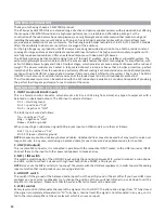
FREQUENCY RESPONSE

LT6A

MODEL

LT6A

LT8A

LT10A

LT12A

LT15A

LT215A

System type

2-way vented enclosure

2-way vented enclosure

2-way vented enclosure

2-way vented enclosure

2-way vented enclosure

2-way vented enclosure

High Frequency Device

1’’ neodymium tweeter

1’’ compression driver 
1" VC

1’’ compression driver 
1.35" VC

1’’ compression driver 
1.35" VC

1’’ compression driver 
1.35" VC

1’’ compression driver 
1.35" VC

Low Frequency Device

6.5” woofer with 1" VC

8” woofer with 1.5" VC

10” woofer with 2" VC

12” woofer with 2.5" VC

15” woofer with 2.5" VC

2x  15” woofer with 2.5" 

VC

Angular Coverage

60° H x 40° V

60° H x 40° V

90° H x 60° V

90° H x 60° V

90° H x 60° V

90° H x 60° V

Total peak power

40

0 W

6

00 W

8

00 W

10

00 W

12

00 W

1

6

00 W

HF Ampli

fi

 er Power

200

 W Class AB

10

0 W Class D

10

0 W Class AB

10

0 W Class AB

1

50 W Class AB

1

5

0 W Class AB

LF Ampli

fi

 er Power

20

0 W Class D

30

0 W Class D

40

0 W Class D

4

50 W Class D

65

0 W Class D

Power Supply type

LINEAR

SMPS

SMPS

SMPS

SMPS

SMPS

Frequency Response

75 Hz - 20 kHz

70 Hz - 20 kHz

60 Hz - 20 kHz

50 Hz - 20 kHz

45 Hz - 20 kHz

45 Hz - 20 kHz

Processing

Analog

Analog

Analog

Analog

Analog

Analog

Max SPL at 1mt (peak)

11

4

 dBspl

12

5

 dBspl

12

7

 dBspl

1

30

 dBspl

1

32

 dBspl

Crossover Frequency

2400 Hz

2200 Hz

2000 Hz

2000 Hz

2000 Hz

Input Impedance

30 kohm balanced
15 kohm unbalanced

3 0   ko h m   b a l a n c e d
15 kohm unbalanced

3 0   ko h m   b a l a n c e d
15 kohm unbalanced

30 kohm balanced
15 kohm unbalanced

3 0   ko h m   b a l a n c e d
15 kohm unbalanced

Input Sensi  vity

LINE: 0/-10 dBu / MIC: 
-20 dBu

LINE: +4 dBu / MIC: -20 
dBu

LINE: +4 dBu / MIC: -20 
dBu

LINE: +4 dBu / MIC: -20 
dBu

LINE: +4 dBu / MIC: -20 
dBu

Controls

MIC/LINE, LEVEL

MIC/LINE, LEVEL, LOW, 
HIGH, GND.

MIC/LINE, LEVEL, LOW, 
HIGH, GND.

MIC/LINE, LEVEL, LOW, 
HIGH, GND.

MIC/LINE, LEVEL, LOW, 
HIGH, GND.

Connectors

M I C / L I N E :   C o m b o 
X L R - F   /   J A C K ,
LINE: RCA, LINK: XLR-M

M I C / L I N E :   C o m b o 
X L R - F   /   J A C K
LINK: XLR-M

M I C / L I N E :   C o m b o 
X L R - F   /   J A C K
LINK: XLR-M

M I C / L I N E :   C o m b o 
X L R - F   /   J A C K
LINK: XLR-M

M I C / L I N E :   C o m b o
X L R - F   /   J A C K
LINK: XLR-M

Power Supply

230 V~ or 120 V~ - 50/60 
Hz

230 V~ or 120 V~ - 50/60 
Hz

230 V~ or 120 V~ - 50/60 
Hz

230 V~ or 120 V~ - 50/60 

Hz

230 V~ or 120 V~ - 50/60 
Hz

Rated Consump  on

1

5

0 W

20

0 W

4

00 W

4

00 W

4

00 W

Construc  on

Plywood

Plywood

Plywood

Plywood

Plywood

Cabinet Colour

Black

Black

Black

Black

Black

Flying System

1 x M4 top / 2 x M4 

bo  om

4 x M8 top/bo  om

4 x M10 top/bo  om

4 x M10 top/bo  om

4 x M10 top/bo  om

Handles

-

1 x rear

1 x rear

2 x sides

2 x sides

Moun  ng Pole

1 x bo  om

1 x bo  om, dual angle

1 x bo  om, dual angle

1 x bo  om, dual angle

1 x bo  om, dual angle

Weight

5.9 kg (13 lb)

8.5 kg (18.7 lb)

12.5 kg (27.6 lb)

16.5 kg (36.4 lb)

21 kg (46.3 lb)

Dimensions (W x H x D)

204 x 295 x 223 mm

220 x 442 x 260 mm

340 x 515 x 310 mm

380 x 595 x 360 mm

448 x 670 x 410 mm

13

8

 dBspl

2000 Hz

3 0   ko h m   b a


l a n c e d


15 kohm unbalanced

LINE: +4 dBu / MIC: -20 
dBu

MIC/LINE, LEVEL, LOW, 

HIGH, GND.

  M I C /


L I N E :   C o m b o  

X L R - F   /   J A C K


LINK: XLR-M

230 V~ or 120 V~ - 50/60 

Hz

8

00 W

Plywood

Black

4 x M10 top/bo  om

2 x sides, 1 x top

1 x bo  om

34 kg (74.9 lb)

448 x 1060 x 450 mm

TECHNICAL SPECIFICATIONS

10k

5k

2k

1k

500

200

100

50

40

20k

Hz

120.0

dBSPL

110.0

100.0

90.0

80.0

70.0

10k

5k

2k

1k

500

200

100

50

40

20k

Hz

120.0

dBSPL

110.0

100.0

90.0

80.0

70.0

10k

5k

2k

1k

500

200

100

50

40

20k

Hz

120.0

dBSPL

110.0

100.0

90.0

80.0

70.0

10k

5k

2k

1k

500

200

100

50

40

20k

Hz

120.0

dBSPL

110.0

100.0

90.0

80.0

70.0

10k

5k

2k

1k

500

200

100

50

40

20k

Hz

120.0

dBSPL

110.0

100.0

90.0

80.0

70.0

10k

5k

2k

1k

500

200

100

50

40

20k

Hz

120.0

dBSPL

110.0

100.0

90.0

80.0

70.0

LT12A

LT8A

LT15A

LT10A

LT215A

Summary of Contents for LT10A

Page 1: ...LT6A LT8A LT10A LT12A LT15A LT215A Ac ve Loudspeakers USER MANUAL ...

Page 2: ...terature indicates that it should not be disposed with other household wastes at the end of its working life To prevent possible harm to the environment or human health from uncontrolled waste disposal please separate this from other types of wastes and recycle it responsibly to promote the sustainable reuse of material resources Household users should contact either the retailer where they purcha...

Page 3: ...LT12A LT15A LT215A CONTROL PANEL FIG 3 8 CONNECTIONS FIG 4 8 CONFIGURATIONS FIG 5 9 SAFETY AND PRECAUTIONS 10 IN CASE OF FAULT 10 TROUBLESHOOTING 10 CE CONFORMITY 11 PACKAGING SHIPPING AND COMPLAINT 11 WARRANTY AND PRODUCTS RETURN 11 INSTALLATION AND DISCLAIMER 11 POWER SUPPLY AND MAINTENANCE 11 GENERAL INFORMATION 12 INSTRUCTIONS FIG 1 2 3 4 5 12 ...

Page 4: ...C LINE LEVEL LOW HIGH GND MIC LINE LEVEL LOW HIGH GND Connectors MIC LINE Combo X L R F J A C K LINE RCA LINK XLR M M I C L I N E C o m b o X L R F J A C K LINK XLR M MIC LINE Combo X L R F J A C K LINK XLR M MIC LINE Combo X L R F J A C K LINK XLR M M I C L I N E C o m b o X L R F J A C K LINK XLR M Power Supply 230 V or 120 V 50 60 Hz 230 V or 120 V 50 60 Hz 230 V or 120 V 50 60 Hz 230 V or 120 ...

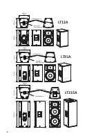
Page 5: ...0 22 0 cm 8 7 34 0 cm 13 4 51 5 cm 20 3 31 0 cm 12 2 44 2 cm 17 4 26 0 cm 10 2 22 3 cm 8 8 29 5 cm 11 6 M4 Flying Point M8 Flying Point Dual angle MounƟng Pole Dual angle MounƟng Pole M10 Flying Point LT6 Pole adapter supplied LT6A LT8A LT10A ...

Page 6: ...7 6 44 8 cm 17 6 36 0 cm 14 2 59 5 cm 23 4 41 0 cm 16 1 67 0 cm 26 4 45 0 cm 17 7 106 0 cm 41 7 M10 Flying Point M10 Flying Point M10 Flying Point Dual angle MounƟng Pole Dual angle MounƟng Pole MounƟng Pole LT12A LT15A LT215A ...

Page 7: ...7 LT6A CONTROL PANEL FIG 1 LT8A CONTROL PANEL FIG 2 ...

Page 8: ...t ring cold INPUT Balanced male XLR ground hot cold INPUT Jack unbalanced ground tip hot cold note connect both cold and ground to make cable from balanced to unbalanced LINK output Balanced female XLR ground hot cold LT10A LT12A LT15A LT215A CONTROL PANEL FIG 3 ...

Page 9: ...LT6A LT8A LT10A LT12A LT15A LT215A stereo basic system 2x LT loudspeaker LT6A LT8A LT10A LT12A LT15A LT215A mic in single voice system LT6A LT8A LT10A LT12A LT15A LT215A mic in single voice system basic conference system set this switch as MIC use preferably balanced cables ...

Page 10: ...uipment capable of producing high sound pressure levels use hearing protectors while the equipment is in opera on Ear plugs or protectors in the ear canals or over the ears must be worn when opera ng the equipment in order to prevent permanent hearing loss if exposure is in excess of the limits set forth here Keep your s a en on that children and pets are more suscep ble to excessive noise levels ...

Page 11: ...efore avoid installa on on unstable elements such as furniture chairs and vibrant surfaces as stages or other speakers without appropriate fix point specifically designed to avoid speaker movement Then avoid the use of inadequate supports we suggest to use CELECTRON stands and accessories only In case of the speakers are provided of rigging points DO NOT SUSPEND THE SPEAKERS FROM THE HANDLES use e...

Page 12: ...oviding the perfect low frequency extension for each model of the series INSTRUCTIONS FIG 1 2 3 4 5 1 INPUT combo XLR JACK input This is a female combo connector which accepts a XLR or a JACK plug from almost any type of equipment with a balanced or unbalanced outputs The XLR input is wired as follows Pin 1 shield or ground Pin 2 posi ve or hot Pin 3 nega ve or cold The JACK input is wired as foll...

Page 13: ...s in the I posi on use this switch to set the speaker power to ON or OFF NOTE When you shut down your equipment turn off the speaker first When powering up turn on the speaker last 11 LINE VOLTAGE selector This switch sets the AC voltage line of your country usually it is set by factory and isn t necessary to change it The 115V se ng is for mains line in the range of 105 120V and 230V se ng is for ...

Page 14: ...Celectron Electronic Group BBFY Industrial USA Inc City of Industry California www celectronaudio com ...

Reviews: