background image

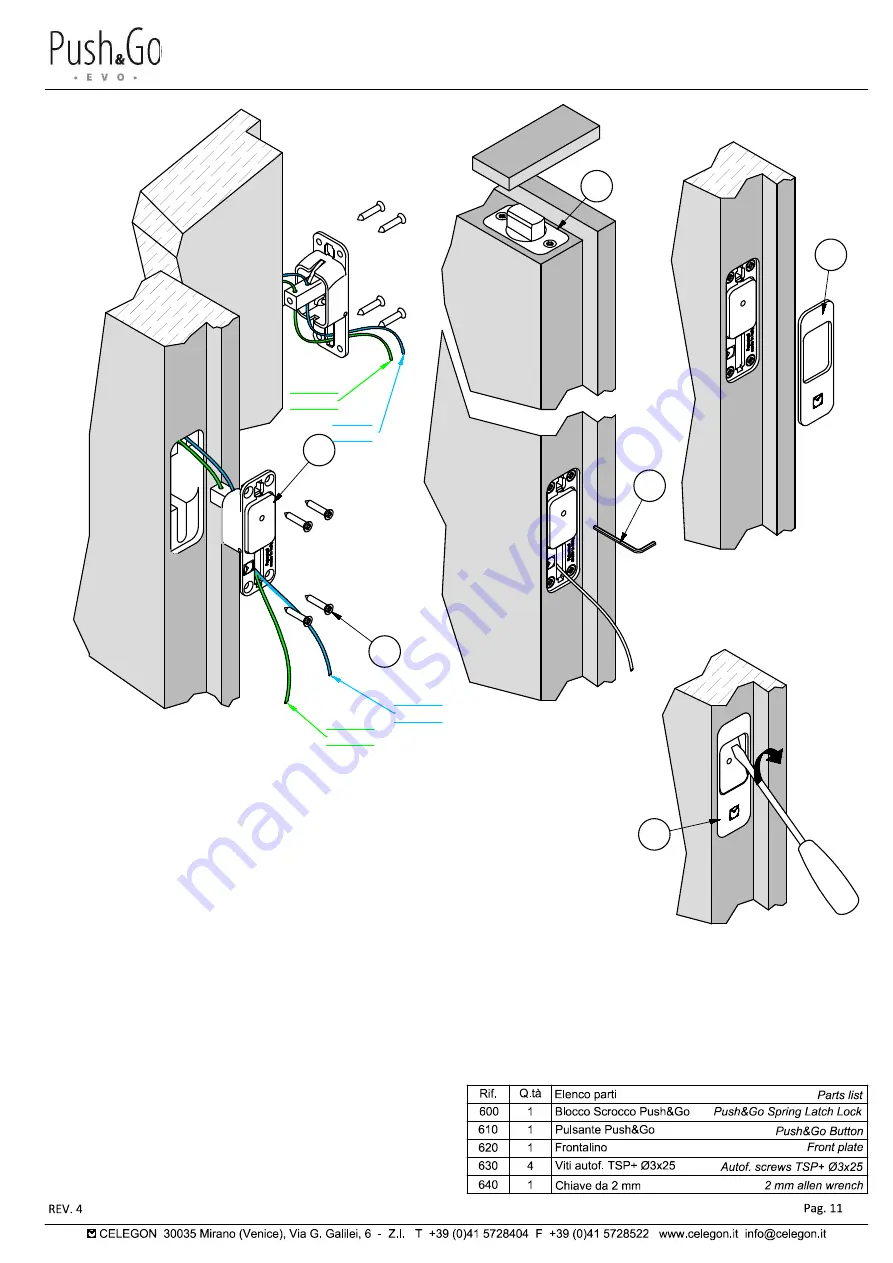
Montaggio pulsante

Assembly of the button

3

4

5

Metal

600

620

630

640

3)

 Inserire il cavetto nel foro (

pos. 1

  o 

pos. 2 

vedi pag. 5-6) posto

sul retro del pulsante 

(610)

 e portarlo sul fronte attraverso la

feritoia.

3)

 Insert the cable in the hole (

pos.1

  or  

pos. 2 see 

page 5-6) on

the back of the button 

(610)

 and bring it to the front through the

slit.

4)

 Prima di fissare il cavetto far uscire completamente lo scrocco

magnetico del blocco superiore 

(600)

 mediante un oggetto

metallico, mettere in tensione il cavetto prestando attenzione a
non abbassare lo scrocco, quindi fissare il cavetto con la chiave

(640)

 in dotazione tramite il foro posto al centro del pulsante.

4)

 Before attaching the cable, let out completely the upper magnetic

spring latch lock 

(600)

 by means of a metallic object, tension the

cable being careful not to lower the spring latch, and then secure
the cable with the allen wrench 

(640)

 supplied through the hole

located in the centre of the button.

5)

 Verificare il corretto funzionamento  del sistema e

successivamente tagliare l'eccedenza del cavetto lasciandolo
sporgere di 2/3 cm, reintrodurre la sporgenza all'interno
dell'anta, applicare il frontalino 

(620)

.

5)

 Check the correct operation of the system and then cut the

excess cable letting it protrude 2/3 cm, reintroduce the

protrusion on the inside of the door, apply the front plate 

(620)

.

610

6

620

6)

 Per togliere il frontalino 

(620)

, premere il pulsante ed

inserire la punta di un cacciavite piano nell'apposita

sede.

6)

 To remove the bezel 

(620)

, press the button and insert

the tip of a flat screwdriver in the specific slot.

POS. 1

POS. 2

POS. 1

POS. 2

Summary of Contents for 4100BR

Page 1: ...MANUALE TECNICO TECHNICAL MANUAL Sistema di sblocco magnetico per porte a doppia anta Magnetic release system for double doors ...

Page 2: ...Sistema di sblocco magnetico per porte a doppia anta Magnetic release system for double doors ...

Page 3: ...Esploso kit Push Go Exploded view Kit Push Go 600 620 610 650 Si possono utilizzare incontri magnetici delle ditte AGB o Bonaiti You can use magnetic strikers of AGB or Bonaiti company 630 630 640 ...

Page 4: ...Utilizzo del sistema Push Go EVO Use of the system Push Go EVO ...

Page 5: ...Utilizzo del sistema Push Go EVO Use of the system Push Go EVO ...

Page 6: ...A B Panoramica delle lavorazioni per l anta Overview of operations for the door 600 600 610 620 620 610 for larger sizes ask Celegon about the feasibility 630 630 ...

Page 7: ...ta sede cavetto milled housing for the cable Nel caso di un anta senza battuta il sistema spessore dell anta In the case of a door without abutment the system may be positioned at the centre of the thickness of the door 25 max cavetto cable cavetto cable 35 POS 2 POS 1 Si possono prevedere il cavetto e lo scrocco magnetico in due posizione diverse in base alle esigenze Cable and magnetic latch can...

Page 8: ... for the cable Sede laterale per pulsante Lateral housing for button E E Sez E E G G Sez G G F F Sez F F 32 10 23 65 6 22 R5 R5 R 3 2 61 2 6 22 16 5 40 prof fresata 32 61 65 3 5 16 5 40 prof fresata 3 5 5 15 min 15 max fresata sede cavetto milled housing for the cable fresata sede cavetto milled housing for the cable fresata sede cavetto milled housing for the cable 15 min 15 min 32 POS 1 25 max P...

Page 9: ...ing from the top side of the door for a length equal to the positioning axis of the button 100 mm listello di copertura fresata incollato con finitura a regola d arte glued and milled cover strip with workmanlike finishing listello di copertura fresata milled cover strip Nel caso di un anta senza battuta al centro dello spessore dell anta In the case of a door without abutment the system may be po...

Page 10: ...re il cavetto all interno della fresata facendolo uscire dalla sede del pulsante sottostante 1 Insert the spring latch lock 600 on the top side of the door let the cable slid within the milled area having it exit from the underlying button housing 2 Fissare lo scrocco mediante le viti 630 2 Fasten the spring latch using the screws 630 600 630 ...

Page 11: ...tely the upper magnetic spring latch lock 600 by means of a metallic object tension the cable being careful not to lower the spring latch and then secure the cable with the allen wrench 640 supplied through the hole located in the centre of the button 5 Verificare il corretto funzionamento del sistema e successivamente tagliare l eccedenza del cavetto lasciandolo sporgere di 2 3 cm reintrodurre la...

Page 12: ...Per la gestione dei binari e profili copribinario vedi manuali tecnici Ergon Living For track and track cover profile see Ergon Living technical manuals ...

Page 13: ...NOTE ...

Page 14: ......

Reviews: