background image


  11


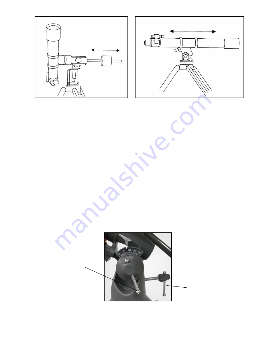
Figure 2-23 


A

A

d

d

j

j

u

u

s

s

t

t

i

i

n

n

g

g


t

t

h

h

e

e


E

E

q

q

u

u

a

a

t

t

o

o

r

r

i

i

a

a

l

l


M

M

o

o

u

u

n

n

t

t


In order for a motor drive to track accurately, the telescope’s axis of rotation must be parallel to the Earth’s axis of 
rotation, a process known as polar alignment.  Polar alignment is achieved NOT by moving the telescope in R.A. or 
Dec., but by adjusting the mount vertically, which is called altitude. This section simply covers the correct 
movement of the telescope during the polar alignment process.  The actual process of polar alignment, that is 
making the telescope’s axis of rotation parallel to the Earth’s, is described later in this manual in the section on 
“Polar Alignment.” 
 

A

A

d

d

j

j

u

u

s

s

t

t

i

i

n

n

g

g


t

t

h

h

e

e


M

M

o

o

u

u

n

n

t

t


i

i

n

n


A

A

l

l

t

t

i

i

t

t

u

u

d

d

e

e


• 

To adjust the latitude of the polar axis, loosen the front latitude adjustment screw (locking bolt) slightly — see  
Figure 2-24. 

 
• 

To increase or decrease the latitude of the polar axis, tighten or loosen the front latitude adjustment screw to 
select the desired latitude.  Then, tighten securely the front latitude adjustment screw. 


The latitude adjustment on the AstroMaster mount has a range from approximately 20° to 60°. 

It is best to always make final adjustments in altitude by moving the mount against gravity (i.e. using the rear 
latitude adjustment screw to raise the mount).  To do this you should loosen both latitude adjustment screws and 
manually push the front of the mount down as far as it will go. Then tighten the rear adjustment screw to raise the 
mount to the desired latitude. 


 Figure 

2-24 

Latitude Adjustment  
Screw  (Rear) 

Latitude Adjustment 
Screw (Locking Bolt) 

Figure 2-22


Summary of Contents for 21064

Page 1: ... IO ON N M MA AN NU UA AL L A As st tr ro oM Ma as st te er r 9 90 0 E EQ Q 2 21 10 06 64 4 A As st tr ro oM Ma as st te er r 1 13 30 0 E EQ Q 3 31 10 04 45 5 A As st tr ro oM Ma as st te er r 9 90 0 E EQ Q M MD D 2 21 10 06 69 9 A As st tr ro oM Ma as st te er r 1 13 30 0 E EQ Q M MD D 3 31 10 05 51 1 ENGLISH ...

Page 2: ...s 15 ASTRONOMY BASICS 16 The Celestial Coordinate System 16 Motion of the Stars 16 Polar Alignment with Latitude Scale 17 Pointing at Polaris 18 Finding the North Celestial Pole 18 Polar Alignment in the Southern Hemisphere 19 Finding the South Celestial Pole SCP 20 Declination Drift Method of Polar Alignment 21 Aligning the Setting Circles 22 Motor Drive 23 CELESTIAL OBSERVING 24 Observing the Mo...

Page 3: ...ll models can be used terrestrially as well as astronomically with the standard accessories included Take time to read through this manual before embarking on your journey through the Universe It may take a few observing sessions to become familiar with your telescope so you should keep this manual handy until you have fully mastered your telescope s operation The manual gives detailed information...

Page 4: ...ovetail Mounting Bracket 10 Accessory Tray 3 RA Setting Circle 11 Tripod 4 Star Pointer Finderscope 12 Counterweight Bar 5 Eyepiece 13 Counterweights 6 Diagonal 14 Equatorial Mount 7 Focus Knob 15 Dec Slow Motion Cable 8 R A Slow Motion Cable 16 Objective Lens 1 2 3 4 5 8 9 7 6 10 11 12 13 14 15 16 ...

Page 5: ...Tube Ring 9 Tripod 3 Telescope Optical Tube 10 Counterweights 4 Primary Mirror 11 Dec Setting Circle 5 Dec Slow Motion Cable 12 Star Pointer Finderscope 6 R A Slow Motion Cable 13 R A Setting Circle 7 Latitude Adjustment Screw 14 Focus Knob 1 2 3 4 13 5 7 8 12 14 11 10 6 9 ...

Page 6: ...n slightly on the tripod leg brace Figure 2 2 The very top of the tripod is called the tripod head 3 Next we will install the tripod accessory tray Figure 2 3 onto the tripod leg brace center of Figure 2 2 4 Insert the cut out in the center of the tray flat side of the tray facing down to match the center of the tripod leg brace and push down slightly Figure 2 4 The ears of the tray should appear ...

Page 7: ...l li in ng g t th he e C Co ou un nt te er rw we ei ig gh ht t B Ba ar r C Co ou un nt te er rw we ei ig gh ht ts s To properly balance the telescope the mount comes with a counterweight bar and two counterweights To install them 1 Remove the counterweight safety screw orange color from the counterweight bar at the opposite end of the threaded rod by unthreading it counterclockwise see Figure 2 12...

Page 8: ...nt Figure 2 16 For the 130 EQ Newtonian the mounting bar is the bracket which is attached to the tube rings For the 90 EQ refractor the mounting bar is attached along the bottom of the telescope tube Before you attach the optical tube make sure that the declination and right ascension locking knobs are tight Figure 2 17 Then make sure that the latitude adjustment screws Figures 1 1 1 2 are tight T...

Page 9: ...ing this make sure the thumb screw is not protruding into the diagonal before inserting the eyepiece 3 The eyepieces can be changed to other focal lengths by reversing the procedure in step 2 above I In ns st ta al ll li in ng g t th he e E Ey ye ep pi ie ec ce es s o on n t th he e N Ne ew wt to on ni ia an ns s The eyepiece or ocular is an optical element that magnifies the image focused by the ...

Page 10: ...weights one at a time 4 Move the counterweights to a point where they balance the telescope i e it remains stationary when the R A lock knob is released 5 Tighten the locking knobs to hold the counterweights in place B Ba al la an nc ci in ng g t th he e M Mo ou un nt t i in n D De ec c The telescope should also be balanced on the declination axis to prevent any sudden motions when the Dec lock kn...

Page 11: ... Mo ou un nt t i in n A Al lt ti it tu ud de e To adjust the latitude of the polar axis loosen the front latitude adjustment screw locking bolt slightly see Figure 2 24 To increase or decrease the latitude of the polar axis tighten or loosen the front latitude adjustment screw to select the desired latitude Then tighten securely the front latitude adjustment screw The latitude adjustment on the As...

Page 12: ...ard in the tube to a single point its focal point Since putting your head in front of the telescope to look at the image with an eyepiece would keep the reflector from working a flat mirror called a diagonal intercepts the light and points it out the side of the tube at right angles to the tube The eyepiece is placed there for easy viewing Newtonian Reflector telescopes replace heavy lenses with m...

Page 13: ...is farther than the one you are currently observing Turning the knob counterclockwise from you allows you to focus on an object closer than the one you are currently observing Note If you wear corrective lenses specifically glasses you may want to remove them when observing with an eyepiece attached to the telescope However when using a camera you should always wear corrective lenses to ensure the...

Page 14: ...e it can have enough brightness for urban areas and yet not be too bright for use in rural areas C Ca al lc cu ul la at ti in ng g M Ma ag gn ni if fi ic ca at ti io on n You can change the power of your telescope just by changing the eyepiece ocular To determine the magnification of your telescope simply divide the focal length of the telescope by the focal length of the eyepiece used In equation...

Page 15: ...oduces a linear field width of 53 feet at a distance of one thousand yards G Ge en ne er ra al l O Ob bs se er rv vi in ng g H Hi in nt ts s When working with any optical instrument there are a few things to remember to ensure you get the best possible image Never look through window glass Glass found in household windows is optically imperfect and as a result may vary in thickness from one part o...

Page 16: ...the next Since the Earth rotates once every 24 hours there are 24 lines total As a result the R A coordinates are marked off in units of time It begins with an arbitrary point in the constellation of Pisces designated as 0 hours 0 minutes 0 seconds All other points are designated by how far i e how long they lag behind this coordinate after it passes overhead moving toward the west M Mo ot ti io o...

Page 17: ... celestial pole is always equal to your latitude If you are observing from Los Angeles which has a latitude of 34 then the celestial pole is 34 above the northern horizon All a latitude scale does then is to point the polar axis of the telescope at the right elevation above the northern or southern horizon To align your telescope 1 Make sure the polar axis of the mount is pointing due north Use a ...

Page 18: ...the Earth s rotational axis Many methods of polar alignment require that you know how to find the celestial pole by identifying stars in the area For those in the northern hemisphere finding the celestial pole is not too difficult Fortunately we have a naked eye star less than a degree away This star Polaris is the end star in the handle of the Little Dipper Since the Little Dipper technically cal...

Page 19: ...d the celestial pole is no longer directly overhead It has moved one degree closer toward the southern horizon This means the pole is now 89 above the southern horizon If you move one degree further north the same thing happens again You would have to travel 70 miles north or south to change your latitude by one degree As you can see from this example the distance from the southern horizon to the ...

Page 20: ...nd di in ng g t th he e S So ou ut th h C Ce el le es st ti ia al l P Po ol le e S SC CP P This method helps improve your polar alignment and gets you closer to the pole that the above methods This will improve your accuracy for more serious observations and photography In each hemisphere there is a point in the sky around which all the other stars appear to rotate These points are called the cele...

Page 21: ...illuminated reticle eyepiece to help you recognize any drift For very close alignment a Barlow lens is also recommended since it increases the magnification and reveals any drift faster When looking due south insert the diagonal so the eyepiece points straight up Insert the cross hair eyepiece and align the cross hairs so that one is parallel to the declination axis and the other is parallel to th...

Page 22: ...moves in R A the setting circle must be aligned each time you want to use it to find an object However you do not need to use a star each time Instead you can use the coordinates of the object you are currently observing Once the circles are aligned you can use them to find any objects with known coordinates The accuracy of your setting circles is directly related to the accuracy of your polar ali...

Page 23: ...d thread it into the hole on the side of the pivot axis Then tighten the bolt with an Allen wrench Figure 4 11 Figure 4 12 Operating the Motor Drive The motor drive is powered by one 9 volt alkaline battery This can power the drive for up to 40 hours depending on motor speed setting and ambient temperature To install the battery unscrew the two mounting screws Figure 4 11 Remove the control panel ...

Page 24: ...not both of its polar caps You will be able to see the cloud belts of Jupiter and the great Red Spot if it is visible at the time you are observing In addition you will also be able to see the moons of Jupiter as they orbit the giant planet Saturn with its beautiful rings is easily visible at moderate power Planetary Observing Hints Remember that atmospheric conditions are usually the limiting fac...

Page 25: ...t sky is inky black Sky Illumination General sky brightening caused by the Moon aurorae natural airglow and light pollution greatly affect transparency While not a problem for the brighter stars and planets bright skies reduce the contrast of extended nebulae making them difficult if not impossible to see To maximize your observing limit deep sky viewing to moonless nights far from the light pollu...

Page 26: ... subject matter Do your photography from a dark sky observing site if possible P Pi ig gg gy yb ba ac ck k P Ph ho ot to og gr ra ap ph hy y Only for the 130 EQ Newtonian telescope piggyback photography is done with a camera and its normal lens riding on top of the telescope Through this method you can capture entire constellations and record large scale nebulae You attach your camera to the piggy...

Page 27: ...ning please call the factory for a return authorization number and price quote C Co ol ll li im ma at ti io on n o of f a a N Ne ew wt to on ni ia an n The optical performance of most Newtonian reflecting telescopes can be optimized by re collimating aligning the telescope s optics as needed To collimate the telescope simply means to bring its optical elements into balance Poor collimation will re...

Page 28: ...t then it may be possible to correct this by re collimating only the primary mirror Procedure Please read this section completely before beginning To star collimate in the Northern Hemisphere point at a stationary star like the North Star Polaris It can be found in the north sky at a distance above the horizon equal to your latitude It s also the end star in the handle of the Little Dipper Polaris...

Page 29: ...ecessary to move the star s image toward the direction of the flaring In this example you would want to move the image of the star in your eyepiece by adjusting the collimation screws toward the three o clock position in the field of view It may only be necessary to adjust a screw enough to move the star s image from the center of the field of view to about halfway or less toward the field s edge ...

Page 30: ...be observed on the lunar surface UHC LPR Filter 1 25 94123 This filter is designed to enhance your views of deep sky astronomical objects when viewed from urban areas It selectively reduces the transmission of certain wavelengths of light specifically those produced by artificial lights Flashlight Night Vision 93588 The Celestron flashlight uses two red LED s to preserve night vision better than r...

Page 31: ...x 10mm at 40 10mm 100x 10mm 65x Angular Field of View w 20mm eyepiece 1 0 1 5 Linear FOV w 20mm eyepiece ft 1000yds 53 79 Mount Equatorial CG3 Equatorial CG3 RA DEC Setting Circles yes yes RA DEC Slow Motion Cables yes yes Tripod Leg diameter 1 25 yes yes CD ROM The Sky Level 1 yes yes Highest Useful Magnification 213x 306x Limiting Stellar Magnitude 12 3 13 1 Resolution Raleigh arc seconds 1 54 1...

Page 32: ...rance CA 90503 U S A Tel 310 328 9560 Fax 310 212 5835 Website www celestron com Copyright 2008 Celestron All rights reserved Products or instructions may change without notice or obligation Item 21064 INST Printed in China 10 00 01 08 ...

Reviews: