background image

ENGLISH | 

1

Congratulations on purchasing the Celestron Smart DewHeater 
and Controller 2x. This controller delivers “smart” and efficient 
power usage for up to two of your telescope system’s dew 
heaters plus another 12V DC device—while also providing cable 
management for your setup. When you plug your dew heaters 
into the controller, one cable connects everything to your power 
source, while another connects the setup to your PC, if desired. 

If you prefer not to connect to a PC, simply plug your dew heaters 
into the controller and power it on. The controller will automatically 
monitor the ambient temperature and humidity using its integrated 
environmental sensor. The thermistor port monitors the lens’s 
temperature and provides only enough power to prevent dew. 
If you’re using battery power, this “smart” system significantly 
reduces the heaters’ power consumption, extending battery life. If 
you would like to manually adjust settings or monitor data, connect 
to a PC or your Celestron mount’s hand control.

1. Parts List

2. Controller Overview

TABLE OF CONTENTS

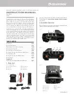
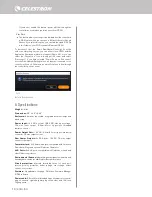
Fig 1 – All included items

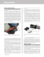
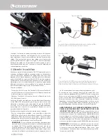
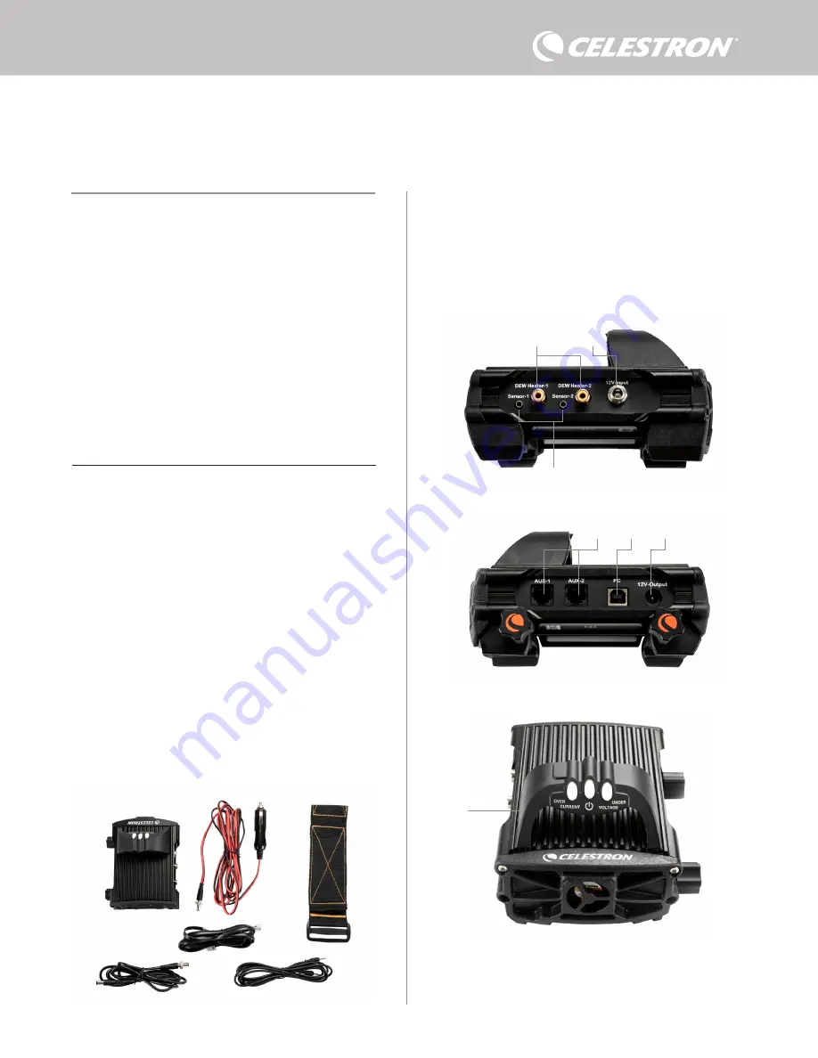
Refer to Figure 2 for an overview of the input jacks, output ports, and 
features of the Smart DewHeater Controller 2x.

If you are missing any parts in the Parts List, please contact Celestron 
Technical Support at

 www.celestron.com/pages/technical-support


for assistance.

1.

 Parts List . . . . . . . . . . . . . . . . . . . . . . . . . . . . . . . . . . . . . . . . . . . . 

Pg.1

2.

 Controller Overview . . . . . . . . . . . . . . . . . . . . . . . . . . . . . . . . . . 

Pg.1

3.

 Mounting the Controller to Your Setup . . . . . . . . . . . . . . . . . . 

Pg.3

4.

 Powering the Controller . . . . . . . . . . . . . . . . . . . . . . . . . . . . . . . 

Pg.4

5.

 Connecting to a Celestron Mount . . . . . . . . . . . . . . . . . . . . . . 

Pg.5

6.

 Using the Controller with a Celestron Hand Control . . . . . . . . 

Pg.5

7.

 Connecting to a PC.  . . . . . . . . . . . . . . . . . . . . . . . . . . . . . . . . . . 

Pg.6

8.

 Using the Controller with CPWI Software . . . . . . . . . . . . . . . 

Pg.7

9.

 Specifications . . . . . . . . . . . . . . . . . . . . . . . . . . . . . . . . . . . . . . . 

Pg.10

Appendix A:


Determining Power Supply Requirement Examples . . . . . . . . . 

Pg.11

SMART DEWHEATER AND CONTROLLER 2X 

INSTRUCTION MANUAL

Model #94035 
ENGLISH

1.


2.


3.

4.

5.

6.

Fig 2-1

Fig 2-2

Fig 2-3

2.


3.


1.


6.


7.


5.


4.


1.

 Smart DewHeater Controller 2x

2.

 Power cable

3.

 Auxilliry cable

4.

 Mount power cable

5.

 Tripod leg strap

6.

 Thermistor Cable

1.

 Dew heater ports 

2.

 Power input jack

3.

 Thermistor ports

4.

 AUX ports

5.

 PC port

6.

 Power output port

7.

 Bridge

Summary of Contents for 94035

Page 1: ...data connect to a PC or your Celestron mount s hand control 1 Parts List 2 Controller Overview TABLE OF CONTENTS Fig 1 All included items Refer to Figure 2 for an overview of the input jacks output p...

Page 2: ...g band or strip it will need an RCA type plug to connect to the controller s heater output ports You have two options for controlling third party bands strips 1 You can purchase the optional Thermisto...

Page 3: ...to the controller or use a power source capable of delivering more current You will need to set the max current draw for your power supply for this LED to work properly as discussed later in this manu...

Page 4: ...and PowerTank 17Ah may not have enough capacity to run your setup all night You ll need a larger capacity battery If you can connect to an AC power outlet you can use an AC to 12V DC adapter If your...

Page 5: ...ct the hand control directly to one of the controller s AUX ports You can also use the included mount power cable to power your mount from the power output port Figure 10 NOTE Power does not flow to t...

Page 6: ...he Dew Heater menu the LCD will display the power draw To disable power to the port to turn off a connected device press ENTER for the selected port The LCD screen will then display Disable port To pr...

Page 7: ...w screen displays the power draw for each port on the controller Figure 14 The icons beside any ports currently in use will turn orange with the power draw over time in the small graph To connect a PC...

Page 8: ...tly from the Overview screen by clicking on the shortcut arrow icon next to the word Power on the upper left side of the Overview screen The Power Graph shows power usage over time for all devices con...

Page 9: ...erent value If you wish to change the color for a value mouse over it and right click You can hide a value from the graph by clicking on the circle to the left of the value s name on the graph To re e...

Page 10: ...ons 5 5 x 4 5 x 3 25 Enclosure Aluminum fan cooled integrated dovetail clamps and tripod strap Power Input 12V DC nominal 13 8V DC max input voltage 10A max input current 5 5mm 2 1mm tip positive thre...

Page 11: ...ating band strip for guidescope approximately 1 0A l Max power required for heating band strip for guidescope 12V x 1 0A 12 0W Celestron CGX EQ mount connected to power port 2 l Max current draw for C...

Page 12: ...relocate the receiving antenna Increase the separation between the equipment and receiver Connect the equipment into an outlet on a circuit different from that to which the receiver is connected Consu...

Page 13: ...ou la commande de votre monture Celestron 1 Liste des pi ces 2 Pr sentation du contr leur SOMMAIRE Fig 1 Tous les l ments inclus Consultez la Figure 2 pour voir la pr sentation g n rale des prises jac...

Page 14: ...plus loin dans le mode d emploi Si vous utilisez une bande ou une languette chauffante de marque autre que Celestron elle aura besoin d une prise de type RCA pour se connecter aux ports de sortie de...

Page 15: ...et e Over Current s allume si la consommation de courant est sup rieure ce que la source d alimentation peut fournir Si cela se produit d connectez ou r duisez l alimentation de l un des appareils con...

Page 16: ...chauffages anti bu e dans des conditions de forte humidit et que vous alimentez galement un appareil 12V CC le contr leur peut fonctionner pr s de sa limite de puissance 120W courant 10A Dans ce cas...

Page 17: ...ciel si n cessaire Vous trouverez la derni re version ici https www celestron com pages drivers and software Pour utiliser la t l commande NexStar ou StarSense connectez le c ble AUX fourni un port AU...

Page 18: ...plus lev pour des ouvertures plus grandes et une activit plus faible si vous utilisez un pare bu e ou s il y a du vent Si vous n tes pas s r du param tre d activit utiliser essayez d abord 5 le param...

Page 19: ...tr leur Pour afficher plus de donn es cliquez sur Aper u APER U L cran Aper u affiche la consommation lectrique de chaque port Si vous utilisez une monture lectronique de Celestron vous pouvez connect...

Page 20: ...ntr le manuel et r glez le curseur sur 0 Si vous s lectionnez le mode automatique vous devrez d finir le niveau activit Il s agit d un nombre de 1 activit la plus faible 10 activit la plus lev e qui i...

Page 21: ...duire la consommation lectrique en r duisant ou en teignant les appareils connect s au contr leur Alternativement vous pouvez utiliser une autre alimentation capable de fournir plus de courant Si vou...

Page 22: ...ions 5 5 x 4 5 x 3 25 Bo tier Pinces queue d aronde et sangle de tr pied en aluminium refroidies par ventilateur et int gr es Entr e d alimentation 12V DC nominal tension d entr e max 13 8V DC courant...

Page 23: ...la bande languette chauffante pour le chercheur environ 1 0 A l Puissance maximale requise pour une bande languette chauffante pour le chercheur 12 V x 1 0 A 12 0 W Monture Celestron CGX EQ connect e...

Page 24: ...R orientez ou d placez l antenne de r ception Augmentez la s paration entre l quipement et le r cepteur Branchez l quipement dans une prise sur un circuit diff rent de celui auquel le r cepteur est c...

Page 25: ...n m chten schlie en Sie einen PC oder die Handsteuerung Ihrer Celestron Montierung an 1 Teile bersicht 2 Steuerungs bersicht INHALTSVERZEICHNIS Abb 1 Alle mitgelieferten Artikel In Abbildung 2 finden...

Page 26: ...Celestron stammt ben tigen Sie einen Cinch Stecker f r den Anschluss an die Heizungsausg nge der Steuerung Sie haben zwei M glichkeiten zur Steuerung von Heizb ndern und streifen anderer Hersteller 1...

Page 27: ...strom leuchtet auf wenn die Stromaufnahme gr er ist als die Stromversorgung liefern kann Trennen Sie in diesem Fall entweder eines der an die Steuerung angeschlossenen Ger te reduzieren Sie ihre Strom...

Page 28: ...e Netzsteckdose zur Verf gung steht k nnen Sie ein 12 VDC Netzteil verwenden Wenn Ihre Ausr stung eine Leistung von 60 W oder weniger 5 A Stromst rke oder weniger ben tigt k nnen Sie das 5 A Netzteil...

Page 29: ...Schlie en Sie dann die Handsteuerung der Montierung wie gewohnt an die Montierung an Alternativ k nnen Sie die Handsteuerung auch direkt an einen der AUX Anschl sse der Steuerung anschlie en Sie k nn...

Page 30: ...chutzniveaueinstellung wenn Sie einen Tauschutz verwenden oder es windig ist Wenn Sie sich nicht sicher sind welche Schutzniveaueinstellung Sie verwenden sollen versuchen Sie es zun chst mit 5 Standar...

Page 31: ...den w hlen Sie Mount USB Montierung USB Wenn Sie das SkyPortal WLAN Modul verwenden tippen Sie auf das Symbol Connection Verbindung und w hlen Sie dann WiFi WLAN CPWI sollte die Steuerung finden und s...

Page 32: ...wenn Sie einen Tauschutz verwenden oder es windig ist Verwenden Sie den Schieberegler um das Schutzniveau einzustellen Wenn Sie sich nicht sicher sind welche Schutzniveaueinstellung Sie verwenden sol...

Page 33: ...nd den Ausgangsstromanschluss der Steuerung angeschlossen sind Jede farbige Linie im Diagramm steht f r einen anderen Anschluss Wenn Sie die Farbe f r einen Anschluss ndern m chten fahren Sie mit der...

Page 34: ...iese Option w hlen finden Sie die gespeicherte CSV Datei in diesem Ordner auf Ihrem PC Dokumente Celestron CPWI Abb 20 Anwendungsabschaltfenster Um die Verbindung zur Intelligenten Tauheizungssteuerun...

Page 35: ...hme f r Heizband Streifen f r Leitrohr ca 1 0 A l Max ben tigte Leistung f r Heizband streifen f r Leitrohr 12 V x 1 0 A 12 0 W Celestron CGX EQ Montierung an Stromanschluss Nr 2 angeschlossen l Max S...

Page 36: ...gsantenne Den Abstand zwischen dem Ger t und dem Empf nger vergr ern Schlie en Sie das Ger t an eine Steckdose an die nicht an den Stromkreis des Empf ngers angeschlossen ist Wenden Sie sich an den H...

Page 37: ...comando manuale della montatura Celestron 1 Elenco componenti 2 Panoramica comando SOMMARIO Fig 1 Tutti i componenti in dotazione Fare riferimento alla Figura 2 per una panoramica dei connettori jack...

Page 38: ...vranno avere una spina di tipo RCA per essere collegata alle porte di uscita del comando anticondensa L utente ha due opzioni per controllare fasce nastri di terzi 1 possibile acquistare il termistore...

Page 39: ...fonte di alimentazione Se ci accade scollegare o ridurre l alimentazione a uno dei dispositivi collegati al comando oppure impiegare una fonte di alimentazione in grado di fornire una quantit maggiore...

Page 40: ...pu essere utilizzato un adattatore da CA a 12 V CC Se la propria configurazione richiede una potenza di 60 W o inferiore corrente 5 A o inferiore possibile utilizzare l adattatore CA Celestron 5 A Pe...

Page 41: ...vo di alimentazione della montatura in dotazione per alimentare la montatura dalla porta di uscita dell alimentazione Figura 10 NOTA L alimentazione non passa attraverso le porte AUX a meno che la mon...

Page 42: ...ere INVIO PORTA DI ALIMENTAZIONE Questa opzione consente di monitorare l uscita di alimentazione da 12 V CC per un dispositivo collegato alla porta di alimentazione Se un dispositivo collegato alla po...

Page 43: ...in uso diventa arancione con un piccolo grafico a destra che indica la potenza consumata Nell angolo in alto a sinistra della schermata Panoramica possibile visualizzare per sistemi anticondensa medi...

Page 44: ...nsa per far apparire la relativa finestra Figura 17 inoltre possibile accedere al Grafico potenza dalla schermata Panoramica facendo clic sulla freccetta del collegamento rapido a fianco alla parola A...

Page 45: ...caldante anticondensa per far apparire la relativa finestra Figura 18 inoltre possibile accedere al Grafico ambiente dalla schermata Panoramica facendo clic sulla freccetta del collegamento rapido a f...

Page 46: ...1 kg 1 2 libbre Dimensioni 13 97 x 11 43 x 8 2 cm 5 5 x 4 5 x 3 25 Scocca Alluminio raffreddamento a freddo fermi a coda di rondine e fascia per treppiede integrati Ingresso alimentazione Tensione di...

Page 47: ...ollegato alla porta del sistema riscaldante anticondensa n 2 l Massimo apporto di corrente a fascia nastro riscaldante per telescopio guida circa 1 0 A l Potenza massima richiesta da fascia nastro ris...

Page 48: ...ntare o riposizionare l antenna di ricezione Aumentare la distanza tra l apparecchiatura e il ricevitore Collegare l apparecchiatura a una presa su un circuito diverso da quello a cui collegato il ric...

Page 49: ...u soporte Celestron 1 Lista de piezas 2 Resumen del controlador NDICE Fig 1 Todos los elementos incluidos Consulte la Figura 2 para un resumen de las tomas de entrada puertos de salida y caracter stic...

Page 50: ...ctar a los puertos de salida de calefactor del controlador Dispone de dos opciones para controlar bandas tiras de terceros 1 Puede adquirir el termistor opcional para controladores de calefactor de co...

Page 51: ...ente de alimentaci n capaz de ofrecer m s corriente Deber establecer el consumo de corriente m ximo para su alimentaci n para que este LED funcione correctamente como se indica m s adelante en este ma...

Page 52: ...instalaci n precisa de 60W de potencia o menos corriente de 5A o menos puede usar el adaptador CA 5A de Celestron Para obtener la conexi n m s segura conecte el cable de salida del adaptador a la tom...

Page 53: ...erg a por los puertos AUX a menos que se conecte un soporte Celestron a uno de los puertos AUX y se encienda Si no tiene conectado un soporte Celestron un mando manual conectado directamente a uno de...

Page 54: ...aci n en el men del calefactor de condensaci n el LCD mostrar el consumo de energ a Para desactivar la alimentaci n al puerto para apagar un dispositivo conectado pulse ENTER para el puerto selecciona...

Page 55: ...el tiempo en la peque a gr fica de la derecha En la esquina superior izquierda de la pantalla Resumen puede ver la energ a total y el consumo de corriente del controlador as como la tensi n de entrada...

Page 56: ...de la pantalla Resumen La gr fica de energ a muestra el uso de energ a con el tiempo de todos los dispositivos conectados a los puertos de calefactor de condensaci n y el puerto de salida de alimentac...

Page 57: ...ulsando el icono de flecha de acceso directo al lado del t rmino Ambiente en la secci n izquierda de la pantalla Resumen Esta gr fica muestra la temperatura del aire ambiente humedad y punto de conden...

Page 58: ...Carcasa Aluminio ventilaci n por ventilador fijaciones machihembradas integradas y correa para tr pode Alimentaci n 12V CC nominal 13 8V CC de tensi n m xima de entrada corriente m xima de entrada 10A...

Page 59: ...lefactor de condensaci n 2 l Consumo m ximo de corriente para banda tira calefactora del catalejo de gu a aproximadamente 1 0A l Potencia m xima necesaria para banda tira calefactora para catalejo de...

Page 60: ...mentar la separaci n entre el equipo y el receptor Conectar el equipo a una toma de un circuito distinto al que est conectado el receptor Consultar al vendedor o a un t cnico experimentado de radio TV...

Reviews: