background image

| ENGLISH

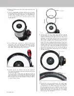
4.   Use a Phillips-head screwdriver to carefully unthread and 

remove the screws that connect the telescope’s corrector 

retaining ring to the front cell (Figure 5). For 5” through 9.25” 

telescopes, there will be six screws to remove. For 11” and 14” 

telescopes, there will be eight screws to remove.  

5.   

Carefully remove the retaining ring from the telescope. 

Also remove the gasket material ring underneath the plastic 

retaining ring.(Figure 5b)

      For 8”, 9.25”, and 11” telescopes only, there are two pins on 

the interior of the front cell that are for the telescope’s lens cap. 

These will interfere with removing the retaining ring. Slightly 

bend the plastic ring to provide clearance with one of the pins 

so you can remove the ring. 

Fig 5

Fig 5b

Retaining Ring

Gasket Ring

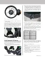
7.   Reinstall the screws removed previously. Only fi nger tighten 

initially. Then, when tightening the screws with your Phillips-head 

screwdriver, use a cross pattern among the screws (Figure 7). 

Only lightly tighten screws at fi rst, so the head of the screw is just 

above the retaining ring. When all screws are lightly installed, 

begin fi nal tightening of the screws, again in a cross pattern.  

Make sure the screws are fi rmly tightened but do not overtighten 

them or you may strip the threads.

Fig 6b

Pin

Notch

Compliance labeling

Dovetail

Fig 6

6.   

Carefully place the dew heater ring where the retaining 

ring was previously. Orient the dew heater ring so that the 

compliance labeling on the ring is just to the right of the 

telescope’s dovetail when looking at the front of the tube 

(see Figure 6). Line up the through holes in the dew heater 

ring with the threaded holes in the telescope’s front cell.
For 8”, 9.25”, and 11” telescopes only, the pins on the interior 

of the front cell will interfere with installation of the of the 

aluminum ring, but there is a notch in the ring’s perimeter to 

account for this. First, place the outer edge of the ring under 

one of the pins. Then, rotate the ring until the notch lines up with 

the other pin (Figure 6b), and you can now seat the ring onto 

the lens cell. Once seated, rotate the ring until it is oriented as 

indicated in Figure 6.

2.   Remove the dust cover and any dew shield connected to the 

optical tube.

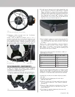
3.   Use the included paper installation shield to cover the optics 

during dew heater ring installation. This will help protect the 

Schmidt corrector lens from inadvertent scratching, fi ngerprints, 

and dust. Place the paper shield over the Schmidt corrector 

so the secondary obstruction fi ts within the central hole in the 

shield (Figure 4).

Fig 4

Summary of Contents for 94050

Page 1: ...ter Ring 11 11 Schmidt Cassegrain produced after 2006 all 11 EdgeHD all RASA 11 94054 Dew Heater Ring 14 14 Schmidt Cassegrain produced after 2006 all 14 EdgeHD all RASA 36cm WARNING The dew heater ring comes in direct contact with the telescope s Schmidt corrector lens and provides mechanical support for this optical element When installing the dew heater ring it will be important not to change t...

Page 2: ...ws are firmly tightened but do not overtighten them or you may strip the threads Fig 6b Pin Notch Compliance labeling Dovetail Fig 6 6 Carefully place the dew heater ring where the retaining ring was previously Orient the dew heater ring so that the compliance labeling on the ring is just to the right of the telescope s dovetail when looking at the front of the tube see Figure 6 Line up the throug...

Page 3: ...highest level of dew prevention but is not the most efficient use of power to keep the optics clear 8 Remove the paper installation shield Installation is now complete When the dew heater ring is not in use the power jack and thermistor jack stay clipped to their plastic storage clips which are connected to the ring itself Figure 8 When in their storage clips the telescope s dust cover can be plac...

Page 4: ... heater rings Figure 13 If you regularly observe in very heavy dew conditions we recommend using both a heater ring and dew shield especially with the larger aperture 11 and 14 models IMPORTANT NOTE Be sure to first remove the dew heater ring s jacks from the integrated clip in the Aluminum Dew Shield before attempting to remove the dew shield from the telescope Otherwise you can damage the jacks ...

Page 5: ...t Schmidt Cassegrain de 9 25 tout EdgeHD de 9 25 94053 Anneau de chauffage anti buée 11 Schmidt Cassegrain 11 produit après 2006 tout EdgeHD de 11 tout RASA 11 94054 Anneau de chauffage anti buée 14 Schmidt Cassegrain 14 produit après 2006 tout EdgeHD de 14 tout RASA 36cm AVERTISSEMENT L anneau de chauffage anti buée entre en contact direct avec la lentille correctrice Schmidt du télescope et fait...

Page 6: ...d endommager les pas de vis Fig 6b Broche Encoche Étiquetage de conformité Queue d aronde Fig 6 6 Placez soigneusement l anneau de chauffage anti buée à la place de l anneau de retenue Orientez l anneau de chauffage anti buée de sorte que l étiquetage de conformité sur l anneau se trouve juste à droite de la queue d aronde du télescope lorsque vous regardez l avant du tube voir Figure 6 Alignez le...

Page 7: ...ip de gestion des câbles inclus Illustration 9 FONCTIONNEMENT AUTONOME Fig 10 Fig 9 8 Retirez le bouclier d installation en papier L installation est maintenant terminée Lorsque l anneau de chauffage anti buée n est pas utilisé la prise d alimentation et la prise jack de thermistance restent attachées à leurs clips de rangement en plastique qui sont connectés à l anneau lui même Figure 8 Lorsqu el...

Page 8: ... d utiliser conjointement un anneau chauffant et un pare buée en particulier avec les modèles à plus grande ouverture 11 et 14 REMARQUE IMPORTANTE Assurez vous d abord de retirer les prises de l anneau de chauffage par rosée du clip intégré dans le pare buée en aluminium avant d essayer de retirer le pare buée du télescope Sinon vous pourriez endommager prises jack et l anneau chauffant pourrait d...

Page 9: ... nach 2006 alle 11 EdgeHD alle RASA 11 94054 Tauheizmanschette 14 14 Schmidt Cassegrain Teleskope die nach 2006 hergestellt wurden alle 14 EdgeHD alle RASA 36 cm ACHTUNG Die Tauheizmanschette kommt in direkten Kontakt mit der Schmidt Korrekturlinse des Teleskops und dient der mechanischen Sicherung dieses optischen Elements Bei der Installation der Tauheizmanschette ist es wichtig Position oder Au...

Page 10: ...entfernt werden 5 Entfernen Sie vorsichtig den Sicherungsring vom Teleskop Entfernen Sie auch den Ring aus Dichtungsmaterial unter dem Sicherungsring aus Kunststoff Abb 5b Nur bei 8 9 25 und 11 Teleskopen befinden sich an der Innenseite der vorderen Zelle zwei Stifte die für die Objektivkappe des Teleskops bestimmt sind Diese behindern das Entfernen des Sicherungsrings Biegen Sie den Kunststoffrin...

Page 11: ...ävention ist aber nicht die effizienteste Nutzung der Leistung um eine klare Sicht durch die Optik beizubehalten 8 Entfernen Sie den Papier Installationsschutz Die Installation ist nun abgeschlossen Wenn die Tauheizmanschette nicht benutzt wird bleiben die Stromversorgungs und die Thermistor Buchse in ihren Aufbewahrungsclips aus Kunststoff festgeklemmt die mit der Manschette selbst verbunden sind...

Page 12: ...insbesondere bei den Modellen mit großer 11 und 14 Öffnung WICHTIGER HINWEIS Achten Sie darauf dass Sie zuerst die Buchsen der Tauheizmanschette vom integrierten Clip im Aluminium Betauungsschutz entfernen bevor Sie versuchen den Betauungsschutz vom Teleskop abzunehmen Andernfalls können Sie die Buchsen beschädigen und die Tauheizmanschette funktioniert nicht mehr Der Celestron Aluminium Betauungs...

Page 13: ...25 94053 Anello riscaldante anticondensa 11 Modelli Schmidt Cassegrain da 11 prodotti dopo il 2006 tutti i modelli EdgeHD da 11 tutti i modelli RASA 11 94054 Anello riscaldante anticondensa 14 Modelli Schmidt Cassegrain da 14 prodotti dopo il 2006 tutti i modelli EdgeHD da 14 tutti i modelli RASA da 36 cm AVVERTENZA L anello riscaldante anticondensa è in contatto diretto con la lente del correttor...

Page 14: ...nello di ritegno dal telescopio Rimuovere inoltre la guarnizione da sotto l anello di ritegno in plastica Figura 5b Nei telescopi da 8 9 25 e 11 sono presenti due perni all interno della cella frontale che sono per il tappo della lente del telescopio Questi interferiscono durante la rimozione dell anello di ritegno Piegare leggermente l anello in plastica per creare spazio tra uno dei perni in mod...

Page 15: ...ZIONAMENTO INDIPENDENTE Fig 10 Fig 9 8 Rimuovere il disco di carta usato per l installazione L installazione è così completata Quando l anello riscaldante anticondensa non è in uso il connettore di alimentazione e il connettore del termistore sono fissati ai rispettivi fermi in plastica che sono collegati all anello stesso Figura 8 Quando i connettori si trovano nei fermi è possibile posizionare l...

Page 16: ...e sia un anello riscaldante sia uno scudo anti rugiada specialmente con modelli con maggiori aperture 11 e 14 NOTA IMPORTANTE Assicurarsi di rimuovere innanzitutto i connettori dell anello riscaldante anticondensa dal fermo integrato nello scudo anti rugiada in alluminio prima di rimuovere lo scudo anti rugiada dal telescopio In caso contrario potrebbero verificarsi danni ai connettori e così rend...

Page 17: ...los Schmidt Cassegrain de 9 25 todos los EdgeHD de 9 25 94053 Arandela calefactora de condensación 11 Schmidt Cassegrain de 11 producidos después de 2006 todos los EdgeHD de 11 todos los RASA 11 94054 Arandela calefactora de condensación 14 Schmidt Cassegrain de 14 producidos después de 2006 todos los EdgeHD de 14 todos los RASA 36cm ADVERTENCIA La arandela calefactora de condensación entra en con...

Page 18: ...o de cumplimiento Machihembrado Fig 6 6 Coloque cuidadosamente la arandela calefactora de condensación donde se encontraba previamente la arandela de retención Oriente la arandela calefactora de condensación de forma que el etiquetado de cumplimiento esté a la derecha del machihembrado del telescopio cuando se mire a la parte anterior del tubo consulte la figura 6 Alinee los agujeros de la arandel...

Page 19: ...cablesincluido figura 9 Fig 10 Fig 9 8 Retire la pantalla de instalación de papel La instalación ha terminado Cuando no se use la arandela calefactora de condensación la toma de alimentación y la toma del termistor quedan enganchadas a sus clips de almacenamiento de plásdtico que están conectados a la misma arandela figura 8 Cuando estén en sus clips de almacenamiento la cubierta para polvo del te...

Page 20: ...rese de retirar primero las tomas de la arandela calefactora de condensación del clip integrado en el protector de condensación de aluminio antes de intentar sacar el protector de condensación del telescopio En caso contrario puede dañar las tomas y dejar inoperativa la arandela calefactora Fig 13 Los protectores de condensación de aluminio de Celestron son totalmente compatibles con las arandelas...

Reviews: