background image


- 12 - 


5.


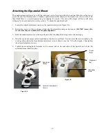
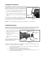
The DEC slow motion knob attaches in the same manner as the R.A. knob.  The shaft that the DEC slow 
motion knob fits over is toward the top of the mount, just below the telescope mounting platform.  Once again, 
you have two shafts to choose from.  Use the shaft that is pointing toward the ground.  This makes it easy to 
reach while looking through the telescope, something which is quite important when you are observing but 
again if it is more convenient for you to use, then reinstall the knob position that suits your needs. 

 
6.


Put the polar axis cap over the polar axis.  It is held into place by a tension fit. 


A

A

t

t

t

t

a

a

c

c

h

h

i

i

n

n

g

g


t

t

h

h

e

e


T

T

e

e

l

l

e

e

s

s

c

c

o

o

p

p

e

e


T

T

u

u

b

b

e

e


t

t

o

o


t

t

h

h

e

e


M

M

o

o

u

u

n

n

t

t


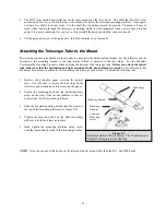
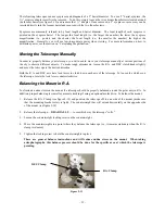
The telescope optical tube attaches to the mount via a dovetail slide bar mounting bracket.  For the refractors and the 
Newtonian, the mounting bracket is the long bracket which is attached to the tube rings.  For the Schmidt-
Cassegrain the mounting bracket is attached along the bottom of the telescope tube

.  Before you attach the optical 

tube, make sure that the declination and right ascension clutch knobs (clamps) are tight.

  This will ensure that 

the mount does not move suddenly while attaching the telescope optical tube.  To mount the telescope tube:  
 
 
1.


Remove the protective paper covering the optical 
tube.  You will have to remove the tube rings on the 
refractors and Newtonian before removing the paper.   

 
2.


Loosen the mounting knob and the mounting safety 
screw on the side of the mount platform so they do 
not protrude into the mounting platform 


3.


Slide the dovetail mounting bracket into the recess on 
the top of the mounting platform (see figure 2-9). 

 
4.


Tighten the mounting knob on the Omni mounting 
platform to hold the telescope in place. 

 
5.


Hand tighten the mounting platform safety screw 
until the tip touches the side of the mounting bracket.  


NOTE: 

Never loosen any of the knobs on the telescope tube or mount other than the R.A. and DEC knobs.


Tube Rings 

Mounting Bracket

Telescope 
Mounting 
Screw 

Mounting 
Platform

Figure 2-9 

Refractor Optical Tube is shown.  The Newtonian and 
Schmidt-Cassegrain attach similarly.  

Summary of Contents for OMNI XLT 102

Page 1: ...s s I IN NS ST TR RU UC CT TI IO ON N M MA AN NU UA AL L O Om mn ni i X XL LT T 1 10 02 2 O Om mn ni i X XL LT T 1 10 02 2E ED D O Om mn ni i X XL LT T 1 12 20 0 O Om mn ni i X XL LT T1 12 27 7 O Om mn ni i X XL LT T 1 15 50 0 O Om mn ni i X XL LT T 1 15 50 0R R ENGLISH ...

Page 2: ...unt in Altitude 17 Adjusting the Mount in Azimuth 17 TELESCOPE BASICS 18 Image Orientation 20 Focusing 20 Aligning the Finderscope 21 Calculating Magnification 21 Determining Field of View 22 General Observing Hints 22 ASTRONOMY BASICS 23 The Celestial Coordinate System 23 Motion of the Stars 24 Latitude Scale 25 Pointing at Polaris 25 Finding the North Celestial Pole 26 Polar Alignment in the Sou...

Page 3: ... a Schmidt Cassegrain 37 Long Exposure Prime Focus Photography 38 Planetary and Lunar Photography with Special Imagers 39 CCD Imaging for Deep Sky Objects 40 Terrestrial Photography 40 Metering 40 Reducing Vibration 40 TELESCOPE MAINTENANCE 41 Care and Cleaning of the Optics 41 Collimation of Refractors 41 Collimation of a Schmidt Cassegrain 42 Collimation of a Newtonian 44 OPTIONAL ACCESSORIES 48...

Page 4: ...ned with Celestron s legendary optical systems give amateur astronomers the most sophisticated and easy to use telescopes available on the market today Take time to read through this manual before embarking on your journey through the Universe It may take a few observing sessions to become familiar with your telescope so you should keep this manual handy until you have fully mastered your telescop...

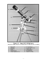
Page 5: ...R refractors are similar 1 Optical Tube 7 1 75 Steel Tripod 2 Tube Rings 8 Accessory Tray Leg Brace 3 Finderscope 9 Counterweights 4 Eyepiece 10 Counterweight Bar 5 Equatorial Mount 11 Dovetail Slide Bar 6 Latitude Adjustment Screw 12 Objective Lens Shade 1 2 3 4 5 6 7 8 9 10 11 12 ...

Page 6: ...1 Finderscope 7 1 75 Steel Tripod 2 Finderscope Bracket 8 Accessory Tray Leg Brace 3 Focuser 9 Counterweights 4 Eyepiece 10 Counterweight Bar 5 Tube Rings 11 Dovetail Slide Bar 6 Equatorial Mount 12 Optical Tube 1 2 4 5 6 7 8 9 10 11 12 3 ...

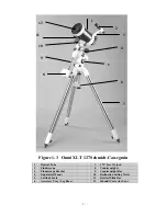
Page 7: ... 7 1 75 Steel Tripod 2 Finderscope 8 Counterweights 3 Finderscope Bracket 9 Counterweight Bar 4 Equatorial Mount 10 Declination Setting Circle 5 Latitude Scale 11 Dovetail Slide Bar 6 Accessory Tray Leg Brace 12 Schmidt Corrector Lens 1 2 3 4 6 7 8 9 10 11 12 5 ...

Page 8: ...is in Figure 2 1 The Omni tripod comes with an all metal center leg brace accessory tray to give rock solid support to the mount The tripod comes fully assembled with a metal plate called the tripod head that holds the legs together at the top In addition there is a central rod that extends down from the tripod head that attaches the equatorial mount to the tripod To set up the tripod 1 Stand the ...

Page 9: ...nt see Figure 2 4 2 Retract the screws so they no longer extend into the azimuth housing on the mount DO NOT remove the screws since they are needed later for polar alignment 3 Hold the equatorial mount over the tripod head so that the azimuth housing is above the metal peg 4 Place the equatorial mount on the tripod head so that the two are flush You can rotate the mount slightly to the center pos...

Page 10: ...a counterweight bar and two counterweights To install the counterweight bar 1 Remove the counterweight safety screw from the counterweight bar opposite of the threaded end 2 Thread the counterweight bar through the counterweight bar locking nut 3 Locate the opening in the equatorial mount on the DEC axis 4 Thread the counterweight bar into the opening until tight 5 Tighten the counterweight bar lo...

Page 11: ... the counterweight safety screw A At tt ta ac ch hi in ng g t th he e S Sl lo ow w M Mo ot ti io on n C Co on nt tr ro ol l K Kn no ob bs s C Ca ab bl le es s The Omni mount comes with two slow motion control knobs cables that allows you to make fine pointing adjustments to the telescope in both R A and Declination To install the knobs 1 Locate the two knobs one is longer than the other and is for...

Page 12: ... bracket is attached along the bottom of the telescope tube Before you attach the optical tube make sure that the declination and right ascension clutch knobs clamps are tight This will ensure that the mount does not move suddenly while attaching the telescope optical tube To mount the telescope tube 1 Remove the protective paper covering the optical tube You will have to remove the tube rings on ...

Page 13: ...nting bracket on the telescope so it does not protrude into the bracket 6 Slide the finder bracket attached to the finderscope into the mounting bracket on the telescope 7 The finderscope bracket will slide in from the back The finderscope should be oriented so that the objective lens is toward the front open end of the telescope 8 Tighten the set screw on the mounting bracket to hold the findersc...

Page 14: ...e image focused by the telescope Without the eyepiece it would be impossible to use the telescope visually The eyepiece fits directly into the focuser of refractors and the Newtonian or into the visual back on the Schmidt Cassegrain To attach an ocular 1 Loosen the set screw on the eyepiece adapter so that it does not obstruct the inner diameter of the barrel 2 Slide the chrome portion of the eyep...

Page 15: ...sen the R A and DEC clutch knobs slightly and move the telescope in the desired direction Both the R A and DEC axis have lock levers to clutch down each axis of the telescope To loosen the clutches on the telescope rotate the lock levers counterclockwise B Ba al la an nc ci in ng g t th he e M Mo ou un nt t i in n R R A A To eliminate undue stress on the mount the telescope should be properly bala...

Page 16: ...rmly to hold the telescope in place Note The Omni XLT150R is the most difficult to balance depending on the latitude the accessories used and which part of the sky the telescope is pointing to Balance this telescope as best you can Like the R A balance these are general balance instructions and will reduce undue stress on the mount When taking astrophotographs this balance process should be done f...

Page 17: ...in ng g t th he e M Mo ou un nt t i in n A Az zi im mu ut th h For rough adjustments in azimuth simply pick up the telescope and tripod and move it For fine adjustments in azimuth Turn the azimuth adjustment knobs located on either side of the azimuth housing see Fig 2 16 While standing behind the telescope the knobs are on the front of the mount Turning the right adjustment knob clockwise moves t...

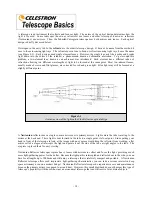
Page 18: ...primary mirror Light enters the tube traveling to the mirror at the back end There light is bent forward in the tube to a single point its focal point Since putting your head in front of the telescope to look at the image with an eyepiece would keep the reflector from working a flat mirror called a diagonal intercepts the light and points it out the side of the tube at right angles to the tube The...

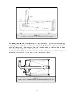
Page 19: ...y short tube lengths making them extremely portable The Schmidt Cassegrain system consists of a zero power corrector plate a spherical primary mirror and a secondary mirror Once light rays enter the optical system they travel the length of the optical tube three times Inside the optical tube a black tube extends out from the center hole in the primary mirror This is the primary baffle tube and it ...

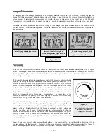
Page 20: ...fle tube The focusing knob which moves the primary mirror is on the rear cell of the telescope just below the star diagonal and eyepiece Turn the focusing knob until the image is sharp If the knob will not turn it has reached the end of its travel on the focusing mechanism Turn the knob in the opposite direction until the image is sharp Once an image is in focus turn the knob clockwise to focus on...

Page 21: ...l for most astronomical finderscopes Because of this it may take a few minutes to familiarize yourself with the directional change each screw makes on the finder C Ca al lc cu ul la at ti in ng g M Ma ag gn ni if fi ic ca at ti io on n You can change the power of your telescope just by changing the eyepiece ocular To determine the magnification of your telescope simply divide the focal length of t...

Page 22: ...ron manufactures is found in the Celestron Accessory Catalog 93685 G Ge en ne er ra al l O Ob bs se er rv vi in ng g H Hi in nt ts s When working with any optical instrument there are a few things to remember to ensure you get the best possible image Never look through window glass Glass found in household windows is optically imperfect and as a result may vary in thickness from one part of a wind...

Page 23: ...ion or DEC for short Lines of declination are named for their angular distance above and below the celestial equator The lines are broken down into degrees minutes of arc and seconds of arc Declination readings south of the equator carry a minus sign in front of the coordinate and those north of the celestial equator are either blank i e no designation or preceded by a plus sign The celestial equi...

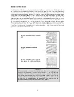
Page 24: ...e because the sunlight during the day washes out the starlight However part of this circular motion of stars in this region of the sky can be seen by setting up a camera on a tripod and opening the shutter for a couple hours The image will reveal semicircles that revolve around the pole This description of stellar motions also applies to the southern hemisphere except all stars south of the celest...

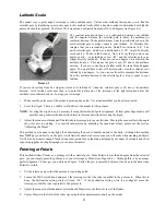
Page 25: ...t you know faces north 2 Level the tripod There is a bubble level built into the mount for this purpose NOTE Leveling the tripod is only necessary if using this method of polar alignment Perfect polar alignment is still possible using other methods described later in this manual without leveling the tripod 3 Adjust the mount in altitude until the latitude indicator points to your latitude Moving t...

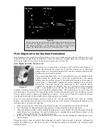
Page 26: ...ar Polaris is the end star in the handle of the Little Dipper Since the Little Dipper technically called Ursa Minor is not one of the brightest constellations in the sky it may be difficult to locate from urban areas If this is the case use the two end stars in the bowl of the Big Dipper the pointer stars Draw an imaginary line through them toward the Little Dipper They point to Polaris see Figure...

Page 27: ...n You would have to travel 70 miles north or south to change your latitude by one degree As you can see from this example the distance from the southern horizon to the celestial pole is always equal to your latitude If you are observing from Sydney which is at latitude 34 then the celestial pole is 34 above the southern horizon All a latitude scale does then is to point the polar axis of the teles...

Page 28: ... st ti ia al l P Po ol le e S SC CP P This method helps improve your polar alignment and gets you closer to the pole that the above methods This will improve your accuracy for more serious observations and photography In each hemisphere there is a point in the sky around which all the other stars appear to rotate These points are called the celestial poles and are named for the hemisphere in which...

Page 29: ...king due south insert the diagonal so the eyepiece points straight up Insert the cross hair eyepiece and align the cross hairs so that one is parallel to the declination axis and the other is parallel to the right ascension axis Move your telescope manually in R A and DEC to check parallelism First choose your star near where the celestial equator and the meridian meet The star should be approxima...

Page 30: ... line up with the R A indicator the zero mark on the vernier scale The R A setting circle should rotate freely If the circle does not move freely loosen the thumbscrew to the right of the scale NOTE Because the R A setting circle does NOT move as the telescope moves in R A the setting circle must be aligned each time you want to use it to find an object This holds true even if you are using an opt...

Page 31: ...ircle If this is the case you will notice that along the vernier scale one of the marks will line up with one of the marks on the setting circle This mark indicates the number of minutes that should be added to the R A reading of the indicator Since the indicator is between two R A marks add the minutes to the lower value that the R A indicator falls between For example let s say the R A indicator...

Page 32: ... H Hi in nt ts s To increase contrast and bring out detail on the lunar surface use optional eyepiece filters A yellow filter works well at improving contrast while a neutral density or polarizing filter will reduce overall surface brightness and glare O Ob bs se er rv vi in ng g t th he e P Pl la an ne et ts s Other fascinating targets include the five naked eye planets You can see Venus go throu...

Page 33: ...ecause of their low surface brightness they should be observed from a dark sky location Light pollution around large urban areas washes out most nebulae making them difficult if not impossible to observe Light Pollution Reduction filters help reduce the background sky brightness thus increasing contrast S Se ee ei in ng g C Co on nd di it ti io on ns s Viewing conditions affect what you can see th...

Page 34: ...er of the objective lens This type of aberration is only evident when observing very bright sources of light such as bright planets and very luminous stars like Sirius There are several techniques that the observer can employ to suppress visible signs of chromatic aberration these include reducing the aperture and using filters The objective lens cap covering the objective lens of the telescope ha...

Page 35: ...st have interchangeable lenses so you can attach it to the telescope and use a variety of lenses for piggyback photography If you can t find a new camera you can purchase a used camera body that is not 100 percent functional The light meter for example does not have to be operational since you will be determining the exposure length manually You also need a cable release with a locking function to...

Page 36: ...hy allows you to capture the entire solar disk if using the proper filter as well as the entire lunar disk To attach your camera to your telescope See note about digital cameras below 1 Remove the eyepiece from the 1 eyepiece holder 2 Unthread the 1 eyepiece holder from the focuser assembly This will expose the male thread of the built in T adapter 3 Thread the T ring onto the exposed T adapter th...

Page 37: ...r camera to the telescope with the eyepiece in place To do so you need two additional accessories a deluxe tele extender 93643 which attaches to the visual back and a T ring for your particular camera make i e Canon Nikon Pentax etc Because of the high magnifications during eyepiece projection the field of view is quite small which makes it difficult to find and center objects To make the job a li...

Page 38: ...ifferent films different focal length eyepieces and even different filters L Lo on ng g E Ex xp po os su ur re e P Pr ri im me e F Fo oc cu us s P Ph ho ot to og gr ra ap ph hy y This is the last form of celestial photography to be attempted after others have been mastered It is intended primarily for deep sky objects objects outside our solar system which includes star clusters nebulae and galaxi...

Page 39: ... 400 T Max 3200 black and white print T Max 400 black and white print As you perfect your technique try specialized films that is films that are designed or specially treated for celestial photography Here are some popular choices Ektar 125 color print Fujichrome 100D color slide Tech Pan gas hypered black and white print T Max 400 black and white print There is no exposure determination table to ...

Page 40: ... in ng g The Omni Series telescopes have fixed apertures and as a result fixed f ratios To properly expose your subjects photographically you need to set your shutter speed accordingly Most 35mm SLR cameras offer through the lens metering which lets you know if your picture is under or overexposed Adjustments for proper exposures are made by changing the shutter speed Consult your camera manual fo...

Page 41: ...t it down This will remove the moisture from the telescope tube To minimize the need to clean your telescope replace all lens covers once you have finished using it Since the cells are NOT sealed the covers should be placed over the openings when not in use This will prevent contaminants from entering the optical tube Internal adjustments and cleaning should be done only by the Celestron repair de...

Page 42: ...w to see if the motion is correct If not undo what you did and try another set of screws After making the first adjustment it is necessary to re aim the telescope tube to center the star again in the field of view It can then be judged for symmetry by going just inside and outside of exact focus and noting the star s pattern Improvement should be seen if the proper adjustments are made Since three...

Page 43: ...kewed 3 Locate the collimation screw closest to where your finger is positioned This will be the collimation screw you will need to adjust first If your finger is positioned exactly between two of the collimation screws then you will need to adjust the screw opposite where your finger is located 4 Use the hand control buttons to move the de focused star image to the edge of the field of view in th...

Page 44: ...le eye damage may result Aligning the Secondary Mirror The following describes the procedure for daytime collimation of your telescope using the optional Newtonian Collimation Tool 94183 offered by Celestron To collimate the telescope without the Collimation Tool read the following section on night time star collimation For very precise collimation the optional Collimation Eyepiece 1 94182 is offe...

Page 45: ...r using the collimation cap Secondary mirror needs adjustment Primary mirror needs adjustment Secondary Mirror Primary Mirror Mirror Clip Both mirrors aligned with the collimating cap in the focuser Both mirrors aligned with your eye looking into the focuser ...

Page 46: ... screws tilt the primary mirror You will start by loosening the small locking screws a few turns each Normally motions on the order of an 1 8 turn will make a difference with approximately a 1 2 to 3 4 turn being the maximum required for the large collimation screws Turn one collimation screw at a time and with a collimation tool or eyepiece see how the collimation is affected see the paragraph be...

Page 47: ...nt screws simultaneously This way you can see exactly which way the movement occurs It may be helpful to have two people working together one viewing and instructing which screws to turn and by how much and the other performing the adjustments IMPORTANT After making the first or each adjustment it is necessary to re aim the telescope tube to re center the star again in the center of the field of v...

Page 48: ...d for low to high power observing The Plössls offer razor sharp views across the entire field even at the edges In the 1 1 4 barrel diameter they are available in the following focal lengths 4mm 6mm 9mm 12 5mm 15mm 20mm 25mm 32mm and 40mm X Cel This 6 element design allows each X Cel Eyepiece to have 20mm of eye relief 55 field of view and more than 25mm of lens aperture even with the 2 3mm In ord...

Page 49: ... operate from 4 D cell batteries not included The hand controller module is very compact and fits easily in the palm of your hand Motors for both axes are included along with brackets clutches and hardware Motor drives are a must for those with a serious interest in astrophotography or CCD imaging NexImage Solar System Imager 93712 NexImage is a complete CCD solar system imager capable of producin...

Page 50: ... high power telephoto lens perfect for terrestrial photography and short exposure lunar and filtered solar photography T Ring The T Ring couples your 35mm SLR camera body to the T Adapter radial guider or tele extender This accessory is mandatory if you want to do photography through the telescope Each camera make i e Canon Nikon Pentax etc has its own unique mount and therefore its own T Ring Cel...

Page 51: ... 1 8kg 4 3 2kg 7 1 8kg 4 3 2kg 7 1 8kg 4 3 2kg 7 1 8kg 4 3 2kg 7 1 8kg 4 3 2kg 7 1 8kg 4 Highest Useful Magnification 240x 240x 283x 360x 360x 300x Lowest Useful Magnification 15x 15x 17x 21x 21x 18x Limiting Stellar Magnitude 12 5 12 5 12 9 13 4 13 4 13 1 Resolution Raleigh arc seconds 1 36 1 36 1 19 0 92 0 92 1 1 Resolution Dawes Limit 1 14 1 14 0 97 0 76 0 76 0 91 Light Gathering Power 212x 212...

Page 52: ...o and excites atoms and molecules in a planet s upper atmosphere Azimuth The angular distance of an object eastwards along the horizon measured from due north between the astronomical meridian the vertical line passing through the center of the sky and the north and south points on the horizon and the vertical line containing the celestial body whose position is to be measured B Binary Stars Binar...

Page 53: ...erstellar cloud of gas and dust Also refers to any celestial object that has a cloudy appearance North Celestial Pole The point in the Northern hemisphere around which all the stars appear to rotate This is caused by the fact that the Earth is rotating on an axis that passes through the North and South celestial poles The star Polaris lays less than a degree from this point and is therefore referr...

Page 54: ...niverse The totality of astronomical things events relations and energies capable of being described objectively V Variable Star A star whose brightness varies over time due to either inherent properties of the star or something eclipsing or obscuring the brightness of the star W Waning Moon The period of the moon s cycle between full and new when its illuminated portion is decreasing Waxing Moon ...

Page 55: ...55 ...

Page 56: ...56 ...

Page 57: ...57 ...

Page 58: ...58 ...

Page 59: ...59 ...

Page 60: ...60 ...

Page 61: ...to abuse misuse mishandling or unauthorized repair Further product malfunction or deterioration due to normal wear is not covered by this warranty CELESTRON DISCLAIMS ANY WARRANTIES EXPRESS OR IMPLIED WHETHER OF MERCHANTABILITY OF FITNESS FOR A PARTICULAR USE EXCEPT AS EXPRESSLY SET FORTH HEREIN THE SOLE OBLIGATION OF CELESTRON UNDER THIS LIMITED WARRANTY SHALL BE TO REPAIR OR REPLACE THE COVERED ...

Page 62: ...ce CA 90503 U S A Tel 310 328 9560 Fax 310 212 5835 Website www celestron com Copyright 2008 Celestron All rights reserved Products or instructions may change without notice or obligation Item 21088 INST Rev 02 Printed in China 10 00 08 08 ...

Reviews: