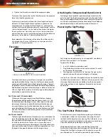
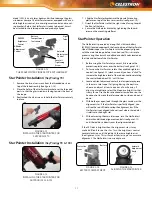
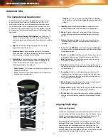
background image

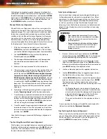
1.  Start out by facing the front of the telescope towards an 
        unobstructed part of the sky, free of any bright lights.

2.  Make sure the cap is removed from the camera lens.

3.     Press the ALIGN button on the hand control to begin the 
        alignment process.

Although SkyProdigy will essentially align itself after pressing 
the ALIGN button, the following is an overview of the StarSense 
alignment process:

• 

SkyProdigy will automatically start moving to its “home 
position”. With the telescope pointed at a clear part of the 
sky, it will slew (move) upwards, away from the horizon 
about 25 degrees.

• 

SkyProdigy will take an image of the sky and display the 
“Acquiring Image” message on the hand control display. 

Once SkyProdigy has begun its alignment process, it 

is important not to touch or move the telescope in any 
way. Also, while imaging the sky, do not obstruct, cover 

or shine light into the camera lens located on the fork 
arm of the mount. Immediately after imaging, SkyProdigy will 
automatically slew to another portion of the sky.

• 

After the first image is taken, the hand control will display 
“Sensing”. During this time the captured image is internally 
processed and will display the number of stars that were 
imaged.

• 

Once processed, the hand control will display the “Solving” 
message as it attempts to positively identify the stars in the 
image.
1.  The hand control will display the “Solved” message 

once it has identified a positive match.

2.  The hand control will display “No Solve” if it is unable 

to identify a match. See “Tips for using SkyProdigy” for 
ways to improve positive alignment matches.   

• 

Once the image has been solved, SkyProdigy will repeat 
this process and display the “Alignment Complete” message 
after three images are successfully acquired. 

SkyProdigy is now ready to start finding and tracking any of the 
objects in its 4,000+ object database.

Tips for Aligning SkyProdigy

Remember the following alignment guidelines to make using 
SkyProdigy as simple and accurate as possible.
•  Be sure to level the tripod before you begin alignment. A 
        level tripod will help the telescope better match the images 
        it takes with the actual sky and give you a more accurate 
        determination of your location.
•  Make sure the tripod legs are sufficiently tight. If there is any 
        noticeable movement in the tripod while aligning the telescope, 
         it may affect results. You may need to tighten both the 
        leg extension locking bolts and the hinge bolts at the top of 
        the tripod. 
•  Make sure that the bottom of the mounting bar on the 
       telescope tube is mounted flush against the bottom of the 
        mounting clamp. If the telescope tube is attached at an 
        angle, it will not be accurately aligned with the camera. 
•  If your SkyProdigy 130 telescope is out of collimation, the optics 
         may no longer be aligned with the optical axis of the camera 
         resulting in unsuccessful alignments or poor pointing accuracy.
•  Once your SkyProdigy 130 has been collimated, it is 
         recommended that you calibrate the camera to match the 
        optics. For information on calibrating the camera, see the 
         Calibrate option under the StarSense Camera section of the 
         manual. 
•  If you notice that the pointing accuracy of the telescope is 
        noticeably worse on solar system objects (planets and the 
        Moon) than it is on stars, you may need to reset the time/
         location information to improve accuracy. Use the Time and 
         Location menu in the hand control to update  time/location 
        information.  


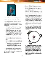
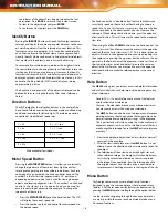
For best alignment results, make sure that your telescope 

is pointed towards an open area of the sky that has a 

clear 

horizon to the right (clockwise) 

of its starting position. 

Once the first alignment image is taken, SkyProdigy 

will move clockwise at least 90° to take a second image 

somewhere between the 4 and 6 o’clock position. If the 

horizon is blocked between the 3 and 6 o’clock position, 

SkyProdigy will continue to move clockwise until it finds 

an unobstructed view of the sky. The third image will be 

taken between the 7 and 9 o’clock position.  The 10 to 12 

o’clock position will only be used if the sky is obstructed in 

its previous position.

13

12

6

7

8

3

4

5

1

2

9

10

11

Summary of Contents for SKY PRODIGY 130

Page 1: ...INSTRUCTION MANUAL I T E M 3 1 1 5 3 COMPUTERIZED TELESCOPE ITEM 22091 SkyProdigy 90 ITEM 22089 SkyProdigy 70 S k y P r o d i g y 1 3 0...

Page 2: ...rPointer Operation HAND CONTROL The Hand Control Aligning SkyProdigy StarSense Alignment Manual StarSense Alignment Solar Sytem Alignment Refine Alignment Object Catalog Selecting an Object Slewing to...

Page 3: ...ELESTIAL OBSERVING Observing the Moon Lunar Observing Hints Observing the Planets Planetary Observing Hints Observing the Sun Solar Observing Hints Observing Deep Sky Objects Seeing Conditions Transpa...

Page 4: ...ranteed to make your observing experience as simple and pleasurable as possible Your SkyProdigy telescope is designed to give you years of fun and rewarding observations However there are a few things...

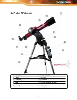
Page 5: ...g Screw 2 Fork Arm 9 Focus Knob 3 On Off Switch 10 Star Diagonal 4 Computerized Hand Control 11 Eyepiece 5 Tripod 12 StarPointer Finderscope not shown 6 Tripod Leg Extension Clamp 13 StarSense Camera...

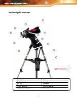
Page 6: ...od 2 StarSense Camera 8 Accessory Tray 3 Fork Arm 9 Star Diagonal 4 On Off Switch 10 Eyepiece 5 Tripod Coupling Screw 11 StarPointer Finderscope 6 Computerized Hand Control 12 Telescope Tube SkyProdig...

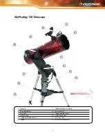
Page 7: ...econdary Mirror 8 Accessory Tray 3 Fork Arm 9 Tripod Coupling Screw 4 On Off Switch 10 StarSense Camera 5 Computerized Hand Control 11 Telescope Tube 6 Tripod 12 StarPointer Finderscope SkyProdigy 130...

Page 8: ...t in the center of the support bracket 4 Finally rotate the tray so that the locking tabs slide under the locking clips on the support bracket You will hear the tray snap into place It is a good idea...

Page 9: ...change the orientation of the star diagonal loosen the thumbscrew on the eyepiece adapter until the star diagonal rotates freely Rotate the diagonal to the desired position and tighten the thumbscrew...

Page 10: ...ng knob until the image is sharp Once an image is in focus turn the knob clockwise to focus on a closer object and counterclockwise for a more distant object If the knob will not turn it has reached t...

Page 11: ...he variable brightness control see figure 2 12 clockwise until you hear a click To increase the brightness level of the red dot continue rotating the control knob about 180 until it stops 3 Locate a d...

Page 12: ...sed in combination with other keys to access more advanced features and functions 8 Enter Pressing ENTER allows you to select any of SkyProdigy s functions accept entered parameters and slew the teles...

Page 13: ...as simple and accurate as possible Be sure to level the tripod before you begin alignment A level tripod will help the telescope better match the images it takes with the actual sky and give you a mor...

Page 14: ...first alignment position Press ENTER Once the third image is processed SkyProdigy is aligned and ready for use Tips for Using Manual StarSense Alignment If SkyProdigy is missing bright objects or not...

Page 15: ...ry stars variable stars and selected asterisms Deep Sky The Deep Sky catalog displays a list of all the best Galaxies Nebulae and Clusters as well as the complete Messier and select NGC objects There...

Page 16: ...choose a speed rate To use this feature simply press the arrow button that corresponds to the direction that you want to move the telescope While holding that button down press the opposite direction...

Page 17: ...et Version Info Selecting this option will allow you to see the current version and build number of the hand control camera and motor control software The first set of numbers indicate the hand contro...

Page 18: ...ffect the slew rates rate 7 9 Cordwrap Cordwrap safeguards against the telescope slewing more than 360 in azimuth and wrapping cables around the base of the telescope This is useful any time that the...

Page 19: ...Hazy Urban Hazy skies combined with light pollution can limit the brightness of stars that the camera can image These setting represents the default setting that should work under most conditions Subu...

Page 20: ...BUTTONS IDENTIFY FILTERS TRACKING SKYTOUR FILTERS CORDWRAP SLEW LIMITS CATALOG FILTERS BACKLASH COMP ALLOW SUN CALIBRATE VIEW MOD LOCATION BACKLIGHT RA DEC VIEW MOD TIME LCD CONTRAST GET VERSION INFO...

Page 21: ...eter Multiplying 3 5 by 60 gives a maximum useful magnification of 210 power Although this is the maximum useful magnification most observing is done in the range of 20 to 35 power for every inch of a...

Page 22: ...detail will be visible So avoid observing the planets when they are low on the horizon or when they are directly over a source of radiating heat such as a rooftop or chimney Refer to the Seeing Condi...

Page 23: ...ing limit deep sky viewing to moonless nights far from the light polluted skies found around major urban areas LPR filters enhance deep sky viewing from light polluted areas by blocking unwanted light...

Page 24: ...uring transport it may have to be collimated The SkyProdigy 70 and 90 have fixed optical systems that should not come out of collimation The SkyProdigy 130 however has three collimation screws that ca...

Page 25: ...Eyepiece 1 7 1 1 9 Linear Field of View at 1000 yds 91feet 53 5 feet 103 feet Eyepiece Magnification 28x 25 mm 50x 25 mm 26x 25 mm 78x 9 mm 139x 9 mm 72x 9 mm Optical Tube Length 27 inches 13 inches 2...

Page 26: ...the positions of stars and planets exert an influence on human affairs astrology has nothing in common with astronomy The distance between the Earth and the Sun It is equal to 149 597 900 km usually r...

Page 27: ...elestial body The brightest stars are assigned magnitude 1 and those increasingly fainter from 2 down to magnitude 5 The faintest star that can be seen without a telescope is about magnitude 6 Each ma...

Page 28: ...means of a mirror The minimum detectable angle an optical system can detect Because of diffraction there is a limit to the minimum angle resolution The larger the aperture the better the resolution T...

Page 29: ...APPENDIX C TIME ZONE MAP 29...

Page 30: ...30 INSTRUCTION MANUAL...

Page 31: ...31...

Page 32: ...ucts or instructions may change without notice or obligation This device complies with Part 15 of the FCC Rule Operation is subject to the following two conditions 1 This device may not cause harmful...

Reviews: