background image

CELIER

SERVICE MANUAL

Xenon 2

RST

Aviation

Adjustment Data and Deflections of the Control

Components

Chapter  8

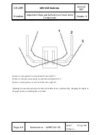
Position 1 corresponds to a rotor head tilt to the left (8°).

Position 2 (vertical) corresponds to a neutral rotor head tilt (0°).

Position 3 corresponds to a rotor head tilt to the right (8°).

Adjusting the neutral position and control stick deflections is performed by changing the length of
the upper pushers controlling the rotor head.

Page  8-6

Document no.:  X2RST-001-PL

Edition 1

24 Aug 2009

Change no.: 

Summary of Contents for Xenon 2 RST

Page 1: ...XCLUDING AIR TRANSPORT USING THIS GYROCOPTER FOR TRAINING AND PRACTICE TO OBTAIN A CERTIFICATE OF QUALIFICATIONS OF AN ULTRALIGHT GYROCOPTER PILOT AS WELL AS HAVE QUALIFICATIONS ENTERED IN THIS CERTIF...

Page 2: ...bsequent amendments It is not allowed to make any entries and supplements in this Flight Manual without the consent of the Civil Aviation Authority In case this Manual is lost you should notify the Ci...

Page 3: ...ed and written in the table below as well as be approved by the Civil Aviation Authority CAA A new or revised text in changed pages must be marked with a black vertical line on the margin and a change...

Page 4: ...SERVICE MANUAL Xenon 2 RST Aviation Organizational Information Chapter 0 Change no Description of change Refers to pages Entry date Signature Page 0 2 Document no X2RST 001 PL Edition 1 24 Aug 2009 Ch...

Page 5: ...8 24 08 2009 2 5 24 08 2009 6 6 1 24 08 2009 2 6 24 08 2009 6 2 24 08 2009 2 7 24 08 2009 6 3 24 08 2009 2 8 24 08 2009 6 4 24 08 2009 2 9 24 08 2009 7 7 1 24 08 2009 2 10 24 08 2009 7 2 24 08 2009 2...

Page 6: ...stems 3 Assembly and Dismantling 4 Service Work Operational Materials 5 Schedule of Overhauls and Service Work 6 Weighing and Specifying the Position of the Centre of Gravity 7 Durability of Structura...

Page 7: ...on Chapter 1 Chapter 1 General Information 1 page 1 1 Introduction 1 2 1 2 Basis for Acknowledging Airworthiness 1 2 1 3 Directives and Announcements of Airworthiness 1 2 1 4 Responsibility 1 3 Editio...

Page 8: ...f Some of the Laws of the Act on Air Law for Some Sorts of Aircraft as well as Defining the Conditions and Requirements concerning the Use of this Craft The detailed conditions and requirements concer...

Page 9: ...The repairs and overhauls of the gyrocopter should be registered with a listing of all defects shortages and additional servicing resulting from the execution of the work schedule in the form of repo...

Page 10: ...CELIER SERVICE MANUAL Xenon 2 RST Aviation General Information Chapter 1 The page is left blank deliberately Page 1 4 Document no X2RST 001 PL Edition 1 24 Aug 2009 Change no...

Page 11: ...al Data 2 2 2 2 Figure in Three Projections 2 3 2 3 Control Systems 2 4 2 3 1 Schema of the Control System with the Rotor 2 4 2 3 2 Schema of the Spring Operated Relieving Device Trimmer 2 5 2 3 3 Sch...

Page 12: ...an Iveco turbocompressor It is equipped with a three blade composite propeller of the DUC brand which has the capability to manually change a stroke The undercarriage is a stationary three wheel one...

Page 13: ...gine type CA 912 ULT Power 122 KM at 5800rpm Reducer ratio 1 2 43 Propeller DUC FC Windspoon R Propeller diameter 1 72m Capacity of fuel tanks 2 42 litres 2 2 Figure in Three Projections variant equip...

Page 14: ...2 3 Control Systems 2 3 1 Schema of the Control System with the Rotor Page 2 4 Document no X2RST 001 PL Edition 1 24 Aug 2009 Change no Lifting Rotor Head Wheel Brake Lever Optionally on the Left or...

Page 15: ...he fair lead 2454 to the grip 2453 with the control stick deflected backwards should amount to 250mm The line should be replaced if any traces of wear are noticed rubbed spots Polyester sailing line w...

Page 16: ...trands Rudder CELIER SERVICE MANUAL Xenon 2 RST Aviation Description of the Gyrocopter and its Systems Chapter 2 2 3 3 Schema of the Directional Control System Page 2 6 Document no X2RST 001 PL Editio...

Page 17: ...and its Systems Chapter 2 2 4 Fuel System Schema Edition 1 24 Aug 2009 Change no Document no X2RST 001 PL Page 2 7 Carburettors Approaching System Airbox T pipe Fuel Regulator Return to Tanks T pipe T...

Page 18: ...tems Chapter 2 2 5 Oil System Schema Page 2 8 Document no X2RST 001 PL Edition 1 24 Aug 2009 Change no Conduit 8mm Oil Tank Hose Dia 12 Hose with Adaptor Gasket Turbine Oil Receptacle Bolts with Locki...

Page 19: ...er and its Systems Chapter 2 2 6 Engine Cooling System Schema Rear View Right Side View Edition 1 24 Aug 2009 Change no Document no X2RST 001 PL Page 2 9 Aluminium Water Pipe Aluminium Water Pipe Alum...

Page 20: ...lity of connecting additional devices Individual circuits are enabled with appropriate marked switches and secured with safety fuses When the generator is idle e g the engine is off it is at a low spe...

Page 21: ...CELIER SERVICE MANUAL Xenon 2 RST Aviation Description of the Gyrocopter and its Systems Chapter 2 Edition 1 24 Aug 2009 Change no Document no X2RST 001 PL Page 2 11...

Page 22: ...ELIER SERVICE MANUAL Xenon 2 RST Aviation Description of the Gyrocopter and its Systems Chapter 2 This page is left blank deliberately Page 2 12 Document no X2RST 001 PL Edition 1 24 Aug 2009 Change n...

Page 23: ...the Rotor 3 4 3 1 4 Fitting the Rotor on the Gyrocopter 3 4 3 2 Assembly Schema of the Rotor Head 3 5 3 3 Assembly Schema of the Rotor Suspension Components on the Mast 3 6 3 4 Prerotation Clutch 3 7...

Page 24: ...T 001 PL Edition 1 24 Aug 2009 Change no 6107 x10 M8x65 Bolt M10 Nut Nylonstop 6102 x2 Steel Sleeve diam 12 6109 x10 M8 Nut Nylonstop Tightening Moment 2 4kGm M6x85 Bolt 6153 x2 Nylon Washer diam 12 6...

Page 25: ...the safety cotter pin and unscrew the nut from the pin for rotor hub suspension in the hub teeter bolt With the help of another person holding down the rotor tuck out the pin making sure the sleeves...

Page 26: ...life of the machine and its subassemblies When the string does not overlap the hub axle two people are needed for help hold down the blade tips then push the hub in the right direction After alignmen...

Page 27: ...10 Main U Component 6118 Stop Base 6122 Bearing d 30 5206 6117 Prerotator Disc 6139 x8 M8 Nut Nylstop 6147 Toothed Wheel Rim 6112 Cotter diam 6 L 2 6 6130 x2 M8x25 Bolt 6140 M8x45 Bolt 6152 x4 M8x25 B...

Page 28: ...y Schema of the Rotor Suspension Components on the Mast Page 3 6 Document no X2RST 001 PL Edition 1 24 Aug 2009 Change no 6114 M10x120 Bolt Cotter Pin 6151 x2 Washer 10x22x2 6115 Spacer Sleeve Nylon 1...

Page 29: ...ion Assembly and Dismantling Chapter 3 3 4 Prerotation Clutch Edition 1 24 Aug 2009 Change no Document no X2RST 001 PL Page 3 7 6207 Brake Foot 6267 Spacer Mandrel 6209 Straining Wheel 6220 Power Whee...

Page 30: ...er component lubricant 3026 x4 Steel Rivets 5x16 3017 x4 M6 Nut Nylonstop 3020 x4 Washer d 6 3034 x4 Washer d 8 3021 x4 M6x50 Bolt lubricant 3037 x4 Shaped Washer d 20 3003 Longitudinal Control Pusher...

Page 31: ...dition 1 24 Aug 2009 Change no Document no X2RST 001 PL Page 3 9 3102A x2 Pusher 3117 Steel Rivet x24 3104 x6 Pusher Tip 3105 x8 M10 Nut 3117 Steel Rivet x24 3100 x8 Ball and Socket Joint d10 3107 x2...

Page 32: ...x2 M10 Nut 3106 x2 M10x45 Bolt lubricant 3107 x2 Nut Nylstop d10x1 5 3120 Washer Nylon d10x30x3 3109 M8 Nut Nylstop 3111 M8x70 Bolt lubricant in the Direction of the Rotor 3112 x2 Washer Nylon d8xD17...

Page 33: ...ly and Dismantling Chapter 3 Edition 1 24 Aug 2009 Change no Document no X2RST 001 PL Page 3 11 3106 x2 M10x60 Bolt 3106 x4 M10 Nut Nylstop 6113 Control Lever V 3108 x4 Steel Spacer Sleeve d10 3x12 5...

Page 34: ...rectional Control System Page 3 12 Document no X2RST 001 PL Edition 1 24 Aug 2009 Change no 1104 Bowden Strand 3 75m 3013 x2 M6 Nut Nylstop 3011 x2 Pusher 12x120 3033 x2 Nut Nylstop 3028 x2 Washer Nyl...

Page 35: ...06 x2 Pedal Unit 3013 x2 M6 Nut Nylstop 3018 x6 Washer Black Nylon d6 4x18x2 Antislip Band 3x 3010 x2 M6 Nut Ball and Socket Joint d8 3013 x2 M6 Nut Nylstop 3033 x2 Nut Nylstop 1 4 28 3028 x4 Washer N...

Page 36: ...ead by means of an electric heater to attenuate the bond through Loctite green and next remove bearing 6122 by means of the press 5 Remove the residue of Loctite by means of sandpaper 6 Apply a new la...

Page 37: ...rational Materials 4 page 4 1 Introduction 4 2 4 2 Range of Service Work which can be Conducted by the Pilot 4 2 4 3 Oil System 4 3 4 4 Engine Head Cooling System 4 3 4 5 Brake Fluid 4 4 4 6 Air Oil a...

Page 38: ...pit interior Repairs inside the cockpit do not require dismantling any structural components or control systems and also they do not collide with these systems or interfere with the gyrocopter structu...

Page 39: ...oil is not correct it is possible to change the position of the oil cooler If you want to change the position of the oil cooler cut the band clips red and move the cooler along the consoles to which i...

Page 40: ...hapter 4 The system capacity amounts to 4 5dm3 All work related to servicing the engine head cooling system including replacing the fluid and rinsing the system is described in the Service Manual of R...

Page 41: ...applicator it must be forced through the system and the old fluid flowing out through the deaerator at the wheel must be gathered into a vessel Make sure the system is deaerated Tighten the deaerator...

Page 42: ...0 5 Rudder hinges 50 hours WHS2002 6 Rudder control pedals 50 hours WHS2002 7 Head tilting pin and the head sloping pin 50 hours WHS2002 8 Pin for rotor hub suspension on the head teeter bolt and slip...

Page 43: ...CELIER SERVICE MANUAL Xenon 2 RST Aviation Service Work Operational Materials Chapter 4 This page is left blank deliberately Edition 1 24 Aug 2009 Change no Document no X2RST 001 PL Page 4 7...

Page 44: ...Introduction 5 2 5 2 Overhauls and Servicing as per Flight Time 5 2 5 3 Overhauls and Servicing as per the Calendar 5 2 5 4 Overhaul after the First 10 25 Hours of Flight 5 3 5 5 Service Work Every 1...

Page 45: ...overhauls should be specified Overhauling and servicing the engine and the systems related to it should be performed according to the instruction manual of the CA 912 ULT engine 5 2 Overhauls and Ser...

Page 46: ...of the rear flexible mounting of the torsional pipe 10 10 5 Checking the condition of rudder bowdens for rubbed spots corrosion excessive friction as well as signs of the wear of the tips Checking the...

Page 47: ...verhauls and Service Work Chapter 5 sprockets Fixing the bendix on the head control lever ensure an apical clearance between the bendix toothed wheels and the toothed wheel rim is about 1 mm Page 5 4...

Page 48: ...are fixed by using blue Loctite The contact surfaces of the stabilizers are sealed with silicone 06 Checking the fixing of the vertical stabilizers to the tail pipes rivets Remove loose or damaged riv...

Page 49: ...he linings occurred unscrew the bolts fixing the brake disc to the wheel hub and check the hammering of the disc Rotor Head Rotor Blades Hub 25 50 100 30 Checking the fixing of the toothed wheel rim t...

Page 50: ...h talc 45 Checking the angle section of the prerotation clutch brake If the angle section is damaged it must be replaced 46 Checking the movement freedom of the drive shafts and clearances in the bear...

Page 51: ...s of the suction lever throttle and prerotation and their passes WHS2002 lubricant 83 Cleaning and lubricating the suction lever and prerotation axles WHS2002 lubricant Do not lubricate the throttle l...

Page 52: ...or rubbed 96 Specifying the weight and position of the centre of gravity of the empty gyrocopter not less than every 4 years After every change of the distribution of weights in the gyrocopter eg aft...

Page 53: ...CELIER SERVICE MANUAL Xenon 2 RST Aviation Schedule of Overhauls and Service Work Chapter 5 This page is left blank deliberately Page 5 10 Document no X2RST 001 PL Edition 1 24 Aug 2009 Change no...

Page 54: ...ying the Position of the Centre of Gravity 6 page 6 1 Introduction 6 2 6 2 Position of the Centre of Gravity and a Datum Reference 6 2 6 3 Weighing and Specifying the CG Position by a Suspension Metho...

Page 55: ...of the centre of gravity of the gyrocopter a sideways view is specified with the value of the angle whose apex is located on the transverse axis of rotor head suspension on the mast one arm is paralle...

Page 56: ...which it was suspended and the weight of the rotor which to be weighed separately The position of the centre of gravity is specified by means of an accurate level accuracy 0 1 held on the upper flat...

Page 57: ...et indications of all the three scales plus the rotor weight provided it was detached when weighing the gyrocopter M WF WRL WRR MR The position of the centre of gravity along axis X is calculated from...

Page 58: ...iation Durability of the Structural Components Chapter 7 Chapter 7 Durability of the Structural Components 7 page 7 1 Introduction 7 2 7 2 Operation Time of the Units 7 2 Edition 1 24 Aug 2009 Change...

Page 59: ...hours or in years from the date of being built in Structural Unit or Component Operation Time Fuselage as a whole 6000 hours Rotor mast 2000 hours replacement Rotor blade hub 2000 hours replacement R...

Page 60: ...Components Chapter 7 Fuel pump 1000 hours or 5 years replacement Fuel conduits 500 hours or 2 years replacement Oil conduits 500 hours or 2 years replacement Fuel tank ventilation ducts 3 years replac...

Page 61: ...Adjustment Data and Deflections of the Control Components 8 page 8 1 Introduction 8 2 8 2 Angular Range of Rotor Head Movements 8 2 8 3 Range of Control Stick Movement 8 4 8 4 Leg Flying Controls Rud...

Page 62: ...lues of the control components along with admissible tolerances and also some adjustment data which must be checked 8 2 Angular Range of Rotor Head Movements Head Deflection Parking position and braki...

Page 63: ...8 Head Tilt The maximum angles of head tilts to the left and right amount to 8 1 1 The extreme values of the deflection and tilting angles of the rotor head are determined by the head structure and i...

Page 64: ...are measured in the horizontal from the cowl panel edge to the centre of the control stick Position 1 corresponds to the extreme front deflection of the rotor head 2 Position 2 vertical corresponds to...

Page 65: ...n 2 RST Aviation Adjustment Data and Deflections of the Control Components Chapter 8 Position 3 corresponds to the extreme rear deflection of the rotor head 19 Edition 1 24 Aug 2009 Change no Document...

Page 66: ...ilt to the left 8 Position 2 vertical corresponds to a neutral rotor head tilt 0 Position 3 corresponds to a rotor head tilt to the right 8 Adjusting the neutral position and control stick deflections...

Page 67: ...o 20 25 to the right and left against the neutral position The values are much higher from the maximum deflection angles which can occur in flight They are not adjustable The relieving flap is preset...

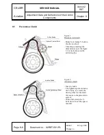
Page 68: ...ns as per the figure 1 2 mm clearance on the activating line Figure 2 Activated clutch Inactive brake The tightening wheel strains the V belts as a result the driving wheel can transmit the torque to...

Page 69: ...Chapter 8 CAUTION When the belts are new before every use of prerotation remember to sprinkle them with children s powder or graphite powder This action will allow the fluent work of the clutch and a...

Page 70: ...SERVICE MANUAL Xenon 2 RST Aviation Adjustment Data and Deflections of the Control Components Chapter 8 This page is left blank deliberately Page 8 10 Document no X2RST 001 PL Edition 1 24 Aug 2009 Ch...

Page 71: ...vice Information Chapter 9 Chapter 9 Other Service Information 9 page 9 1 Manoeuvring on the Ground Road Transport 9 2 9 2 Cleaning and Maintenance 9 2 9 3 Repairs and Modifications 9 2 Edition 1 24 A...

Page 72: ...he automotive type Soft fabrics or suede must be used for polishing The glazing is to be rinsed with clean water or a water solution with an addition of mild soap and next wiped up with clean soft fab...

Page 73: ...n 2 RST Aviation List of Notices and Markings Chapter 10 Chapter 10 List of Notices and Markings 10 Page 10 1 Introduction 10 2 10 2 Notices and Markings 10 2 Edition 1 24 Aug 2009 Change no Document...

Page 74: ...raight ahead of the pilot one of the presented plaques depending on the scaling of the speedometer Ballast equalization plaque for solo flights Page 10 2 Document no X2RST 001 PL Edition 1 24 Aug 2009...

Page 75: ...e 2 pieces Description of the control lever CHOKE suction BENDIX toothed clutch PREROTATOR prerotation clutch THROTTLE On the central console Do not grip On the outside of both winglets of the horizon...

Page 76: ...witch On the central console Starter On the instrument board under the start up button Fuel pump On the central console Magnetos On the instrument board under the switches Microphone and earphone sock...

Page 77: ...on List of Notices and Markings Chapter 10 Trimmer Electric sockets On the left side of the instrument board over the socket On the central console before the trimmer strand Edition 1 24 Aug 2009 Chan...

Page 78: ...MANUAL Xenon 2 RST Aviation Supplements Chapter 11 Chapter 11 Supplements 11 page 11 1 Introduction 11 2 11 2 List of Introduced Supplements 11 2 Edition 1 24 Aug 2009 Change no Document no X2RST 001...

Page 79: ...equipped with various additional systems and equipment not applied in the standard variant 11 2 List of Introduced Supplements Document no Title of an attached supplement Notes In the Notes column co...

Reviews: