background image

20’ x 20’ / 6m x 6m Bexley Series Frame Canopy

www.GetTent.com / www.CelinaTent.com

PG.5

© 2013 Celina Tent Inc. 

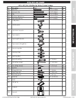
REQUIRED HARDWARE

SAFETY

MAINTENANCE

INS
TALLA
TION

CONT
AC

TS

20’ x 20’ / 6m x 6m Bexley Series Frame Canopy

#

Description

Part

Size

Qty

#01

Roof Pole

56.3” / 1430mm

16

#02

Horizontal Pole

75.4”/ 1915mm

27

#03

Leg

97.9” / 2488mm

8

#04

Horizontal Gable Brace

57.9” / 1470mm

8

#05

Vertical Gable Brace

19.7” / 500mm

4

#06

3 Way Corner

4

#07

Side Connector

4

#08

Top Corner Connector

2

#09

Top Connector

2

#10

Top Straight Connector

4

#11

Top Connector Straight End

4

#12

Corner Ground Bar

4

#13

Side Ground Bar

4

#14

End Ground Bar

4

#15

Spiral Ground Peg

13” / 330mm

4

#16

Ground Pegs (Large)

12” / 304.8mm

8

#17

Ground Pegs (Small)

7” / 177.8mm

36

#18

Eye Bolt

122

#19

Wingnut & Screws

1” / 25.4mm

16

#20

Long Bungeeball

8” / 203.2mm

112

#21

Short Bungeeball

5” / 127mm

26

#22

Guy Rope

96” / 2438.4mm

4

#23

Hook

8

#24

Canopy Top

1

#25

Sidewalls

6

#26

Endwalls

2

Summary of Contents for BEXLEY SERIES

Page 1: ...et structural code unless specified Since weather is unpredictable the installer end user must incorporate their own good judgment common sense and knowledge of local conditions with the installation...

Page 2: ...indow sidewalls at each bay and has a convenient zipper entrance exit door on each gable end wall Suggested Equipment Drop cloth or ground cloth Bexley Series Frame Canopy Tent Specifications Width 20...

Page 3: ...ult in serious personal injury DO NOT OVER LIFT The equipment may be heavy and may require 2 or more people to lift and move DO NOT OVERREACH Keep proper footing and balance at all times Use a ladder...

Page 4: ...esponsibil ity to be sure the staking is adequate for each site on each setup Additional staking tiebacks and or stake bars may be required in order to safely setup and secure the product The number o...

Page 5: ...1470mm 8 05 Vertical Gable Brace 19 7 500mm 4 06 3 Way Corner 4 07 Side Connector 4 08 Top Corner Connector 2 09 Top Connector 2 10 Top Straight Connector 4 11 Top Connector Straight End 4 12 Corner...

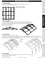
Page 6: ...use a drop cloth to keep top free of damage b Place the top over the assembled frame by spreading the tent out on one end and flapping the top while pulling it over the frame c Attache the top to the...

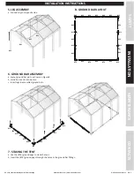
Page 7: ...02 14 14 14 14 12 12 12 12 13 13 13 13 02 02 02 02 02 14 14 13 13 12 12 12 B GROUND BAR LAYOUT 5 LEG ASSEMBLY a Connect legs on opposite side 6 GROUND BAR ASSEMBLY a Layout ground bar parts a shown on...

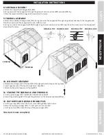
Page 8: ...of the bungee ball around itself to secure INSTALLATION INSTRUCTIONS SAFETY MAINTENANCE INSTALLATION CONTACTS 10 LEG DRAPE ASSEMBLY a Attached the triangle end of the hook 23 through each elastic loo...

Page 9: ...s or holes Repair kits and tools are avail able online at www GetTent com or by contacting Celina Celina Tent Inc warrants that this product will be free from defects in material and workmanship for a...

Page 10: ...400 STATE CENTER PHONE New York Dig Safely New York 800 926 7962 New York City Long Island One Call 800 272 4480 North Carolina North Carolina One Call 800 634 4949 North Dakota North Dakota One Call...

Reviews: