20’ x 20’ / 6m x 6m Bexley Series Frame Canopy
www.GetTent.com / www.CelinaTent.com
PG.6
© 2013 Celina Tent Inc.
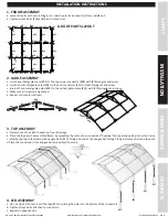
1. FRAME ASSEMBLY
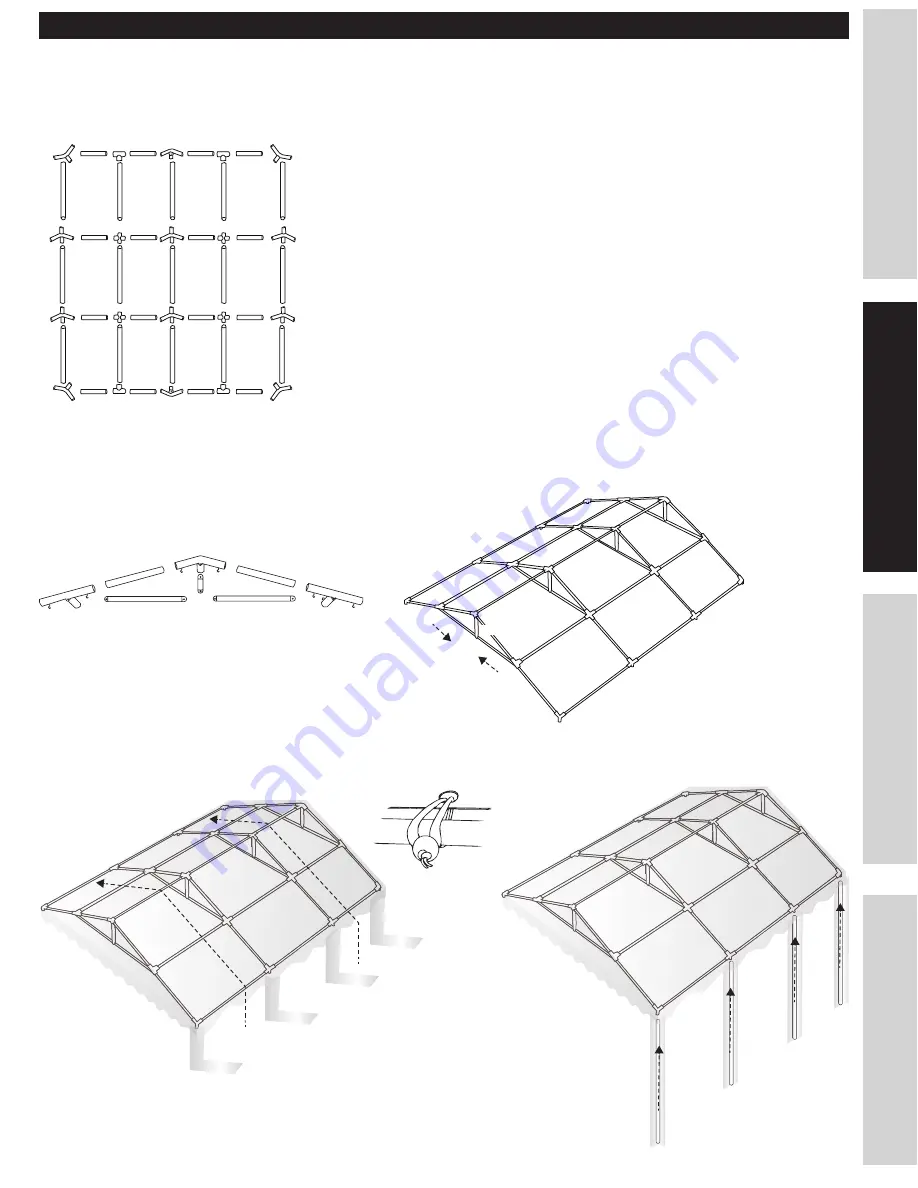
a. Layout all parts as shown in Diagram A. Join all poles and connectors from middle out.
b. Tighten all eye bolts (#18) attached to connectors.
2. GABLE ASSEMBLY
a. Join the vertical gable brace (#05) to the top corner connector (#08) with (#19)wingnut and screw.
b. Join the horizontal gable poles (#04) to the end connectors (#11) with (#19)wingnut and screw.
c. Join both horizontal gable poles (#04) to the vertical gable brace (#05) with (#19) wingnut and screw.
d. Make sure all screws are tightened.
e. Repeat at all center sections.
3. TOP ASSEMBLY
a. Always use a drop cloth to keep top free of damage.
b. Place the top over the assembled frame, by spreading the tent out on one end and “flapping” the top while pulling it over the frame.
c. Attache the top to the frame with bungee balls (#20). String one end of the bungee ball through the grommet and around the pole.
d.Place the round end of the bungee ball around itself to secure.
SAFETY
MAINTENANCE
INS
TALLA
TION
CONT
AC
TS
INSTALLATION INSTRUCTIONS
#06
#07
#07
#07
#07
#06
#01
#01
#01
#01
#01
#01
#01
#01
#01
#01
#01
#01
#02
#02
#02
#02
#02
#02
#02
#02
#02
#02
#02
#02
#02
#02
#02
#11
#10
#10
#10
#10
#11
#08
#09
#09
#06
#06
#01
#01
#01
#01
#11
#11
#08
#01
#11
#08
#05
#04
#04
#04
#04
#08
#09
#10
#05
#03
#03
#03
#03
A. ROOF PARTS LAYOUT
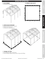
4. LEG ASSEMBLY
a. On one side of the tent insert the legs (#03) by sliding the pole into the bottom of the connectors.
b. Tighten all eye bolts attached to connectors.
c. Repeat on opposite side.

