www.cellarcool.com | Page 17
WM & FD Twin
INSTALLING THE FULLY DUCTED EVAPORATOR UNITS
1.
Using 1/4” and 3/8” copper tubing, route the liquid and suction
lines through the knockouts in the housing. Be sure to extend
the tubing far enough outside of the housing to extend
through the wall if necessary.
2.
Wrap both sides of the copper tubing to prevent overheating.
3.
To prevent oxidation, purge the system with nitrogen.
4.
Braze the copper tubing to the connections on the
evaporator unit.
5.
Insulate the suction line using Armaflex or similar insulation.
6.
Using the cable ties and cable tie mounts provided, secure
the drain line to the bottom of the housing to ensure a
downward slope.
7.
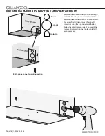
Route the power wire, display cable, and the bottle connector
through the knockouts.
8.
Connect the power wires according to color: connect the
ground wire to the green wire, the hot wire to the black wire,
and the neutral wire to the white wire.
9.
Locate the thermostat wire connections inside of the master
unit.
10.
Connect the 18-5 wire that was routed between the
evaporator units according to color (yellow to yellow, red to
red, and green to green).
11.
Install the supplied black strain relief to secure the power
supply wires and bottle probe wire in the housing.
12.
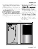
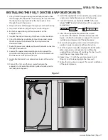
Connect the display cable labeled “
UNIT
” to the wire
labeled “
UNIT
” located in the bottom of the evaporator
compartment.
UNIT
UNIT
13.
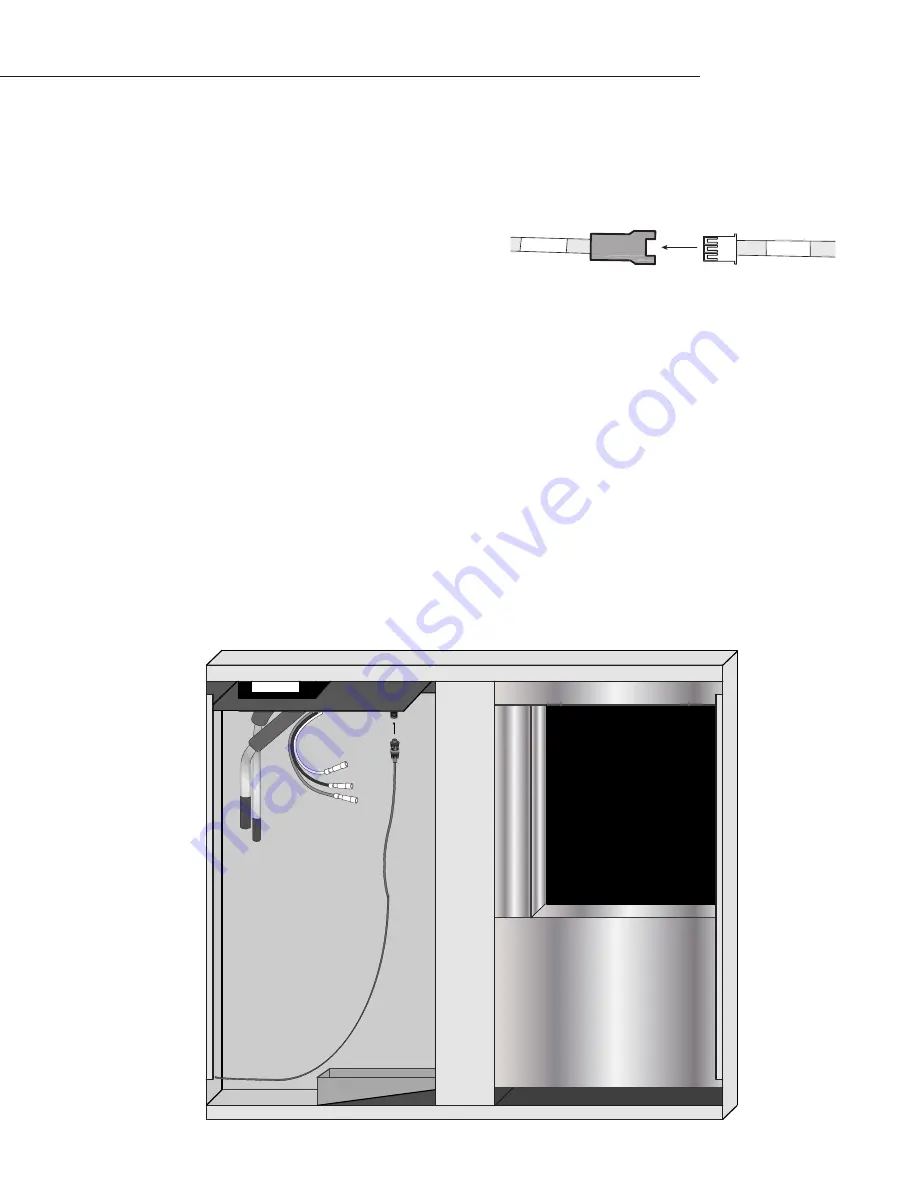
Attach the supplied bottle probe to the circular
connector on the bottom of the electrical panel. (See
Figure 1.) Follow the directions on page 21 for correct
installation and placement of the bottle probe.
14.
Secure all wiring neatly and as close to the left wall as
possible in order to minimize airflow obstruction.
15.
Seal the air gaps around the display cable, bottle probe
cable, and power wire knockouts by installing the
supplied three-inch pieces of cork tape. (For best results,
install the cork tape inside of the unit.)
16.
Repeat steps 1-15 with the second evaporator unit.
(Steps 12 and 13 do not apply to the slave unit.)
17.
Follow the instructions on page 37 for correct installation
of the ducted plenum.
46375
Figure 1


