background image

1

ENGLISH

Before using the tool, read and understand fol-

lowing instructions. Failure to so could result in 

DEATH or SERIOUS INJURY.

Explanations of symbols marked on the tool.

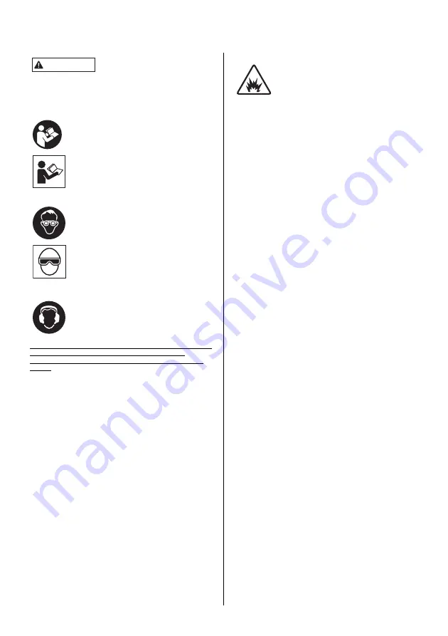
Before using the tool, read and understand tool 
labels, Safety instructions manual and Operating 
instructions manual. Failure to follow warnings 
could result in serious injury. 
Keep these instructions with the tool for future ref-
erence.
Additional copies of this manual, operating in-
structions manual and tool labels are available 
online. For further information, contact us at our 
web page.
Operators and others in work area shall wear 
impact-resistant eye protection with side shields. 
Danger to the eyes always exists due to the pos-
sibility of dust being blown up by the exhausted 
air or of a fastener flying up due to the improper 
handling of the tool. 
Eye protection equipment must conform to the re-
quirements of the American National Standards 
Institute, ANSI Z87.1 (Council Directive 89/686/
EEC of 21 DEC. 1989).
The employer is responsible to enforce the use of 
eye protection equipment by the tool operator and 
all other personnel in the work area.
As the working condition may include exposure to 
high noise levels which can lead to hearing dam-
age, the employer and user should ensure that 
any necessary hearing protection is provided and 
used by the operator and others in the work area.

EMPLOYERS, TOOL OWNERS AND TOOL OPERATORS ARE 
RESPONSIBLE FOR THE SAFE USE OF THIS TOOL
AND COMPLIANCE WITH ALL WARNINGS AND INSTRUC-
TIONS.

At a Minimum, Employers, Tool Owners and 

Tool Operators Must: 

1. ensure that the manufacturer’s tool operating/safety instruc-

tions, warnings and labels are available to all tool operators 
and users. Do not use tool with missing or damaged safety 
warning label(s.);

2. select an appropriate tool actuation (trigger) system from the 

options available, taking into consideration the work applica-
tions for which the tool is being used. Contact Celo authorized 
distributors for information on actuation systems options; 

3. train tool operators and users in the safe use of the tool as de-

scribed in the tool operating/safety instructions, warnings and 
labels;

4. allow only persons who have read and understood the tool op-

erating/safety instructions, warning and labels to operate the 
tool. 

5. allow tool use only when tool operator and all other personnel 

in work area are wearing appropriate eye protection equip-
ment, and when required, other appropriate personal protec-
tive equipment, such as, head, hearing and foot protection 
equipment. Provide information about the safe duration of use 
and appropriate working positions.

AVOID EXPLOSION HAZARD

1

Only use approved power source. Never use reactive high 
pressure or combustible gases (e.g., oxygen, carbon diox-
ide, acetylene, flammable gases etc.) as a power source.

2

Do not operate the tool in explosive atmospheres, such as 
in the presence of flammable liquids, gases or combustible 
dust.

General safety rules

1

Keep fingers away from trigger when not operating this tool 
and when moving from one operating position to another.

2

Keep all body parts such as hands and legs etc. away from 
firing direction and ensure fastener cannot penetrate work-
piece into parts of the body. 

3

Read and understand the safety instructions before con-
necting, disconnecting, loading, operating, maintaining, 
changing accessories on, or working near the tool. Failure 
to do so can result in serious bodily injury.

4

Place the nail discharge outlet of the tool on the work sur-
face properly when operating. Failure to place the dis-
charge outlet in a proper manner can result in fasteners 
shooting away from the work surface and is extremely dan-
gerous. 

5

Hold the tool with a firm grasp and be prepared to manage 
recoil. 

6

Only technically skilled operators should use tool.

7

Do not modify tool. Modifications may reduce the effective-
ness of safety measures and increase the risks to the oper-
ator and/or bystander.

8

When operating a tool intended to be used on hard surfaces 
such as steel and concrete, put additional down force re-
quired to operate the tool and prevent slipping. 

9

Do not use a tool if the tool has been damaged or is not in 
proper working order. Tag and physically segregate tool to 
prevent use.

0

Be careful when handling fasteners, especially when load-
ing and unloading, as the fasteners have sharp points which 
could cause injury. 

a

Always check the tool before use for broken, misconnected 
or worn parts. 

b

Do not overreach. Only use in a safe working place. Keep 
proper footing and balance at all times. 

c

Keep bystanders and children away (when working in an 
area where there is a likelihood of through traffic of people). 
Clearly mark off your operating area. 

d

Never point the tool at yourself or others. Serious accidents 
may be caused when misfiring. Be sure the discharge outlet 
is not pointed toward people when connecting and discon-
necting the hose, loading and unloading the fasteners or 
similar operations.

e

Do not rest your finger on the trigger when picking up the 
tool, moving between operating areas and positions or 
walking, as resting finger on trigger can lead to inadvertent 
operation.

f

Only wear gloves that provide adequate feel and safe con-
trol of triggers and any adjusting devices.

g

When not in use, disconnect tool from power supply, re-
move fasteners and lay it on its side in a safe location. 

h

Always refer to tool maintenance instructions for detailed in-
formation on proper maintenance of the tool. Only qualified 
personnel shall repair the tool using parts supplied or rec-
ommended by Celo or parts that perform equivalently. 

WARNING

Summary of Contents for FORCE ONE

Page 1: ...p these instructions with the tool for future reference Bitte lesen Sie sich die Anweisungen und Warnungen f r dieses Werkzeug vor der Verwendung sorgf ltig durch Anderenfalls k nnte dies zu schweren...

Page 2: ...Fig 1 Fig 2 Fig 3 Fig 4 Fig 5 Fig 6 Fig 7 Fig 8 Fig 9 Fig 10 Fig 11 Fig 12 d f h e i k j g l 1 3 9 2 5 4 6 7 8 0abc 2 1 1 2 3 1 2 1 2 1 1 1 1 2 3 2 1 1 3 4...

Page 3: ...Fig 13 Fig 14 Fig 15 Fig 16 Fig 17 Fig 18 Fig 19 2 1 2 1 2 1 2 1 1 2 1...

Page 4: ...h pressure or combustible gases e g oxygen carbon diox ide acetylene flammable gases etc as a power source 2 Do not operate the tool in explosive atmospheres such as in the presence of flammable liqui...

Page 5: ...cessories 2 During operation be careful that fasteners penetrate mate rial correctly and cannot be deflected misfired towards op erator and or any bystanders 3 During operation debris from workpiece a...

Page 6: ...with specified charger If charged with other charg er it could fail to be properly charged as well as get broken ignited or generate the heat 3 Charge the Battery at the specified voltage Never charg...

Page 7: ...fastener STORAGE 1 When not in use for an extended period apply a thin coat of the lubricant to the steel parts to avoid rust 2 Do not store the tool in a cold weather environment Keep the tool in a...

Page 8: ...ger 0 Follower k Power Plug a Follower Holder l AC Adapter PRODUCT NO FORCE ONE HEIGHT 365 mm 14 3 8 WIDTH 124 mm 4 7 8 LENGTH 334 mm 13 1 8 WEIGHT 3 6 kg 7 9 lbs Including Battery LOADING CAPACITY 22...

Page 9: ...to the hand arm system when using the tool will for example depend on the gripping force the con tact pressure force the working direction the adjustment of energy supply the workpiece the workpiece...

Page 10: ...rature sup ply voltage or remaining battery capacity Once charg ing is fully completed the green LED will be illuminated to inform you that charging has been com pleted If the fully charged Battery is...

Page 11: ...tery is low the red LED of the tool will be turned on 1 Fig 2 Firmly holding the grip press the latches 2 on both sides of the Battery 1 to remove it 2 Install the newly charged Battery into the Housi...

Page 12: ...ben ist 4 nur Personen gestatten das Werkzeug zu bedienen die die Betriebs und Sicherheitsanweisungen f r das Werkzeug die Warnungen und die Beschriftungen gelesen und verstanden haben 5 die Verwendun...

Page 13: ...L sen Sie das Werkzeug nur aus wenn es fest gegen das Werkst ck gepresst ist m Betrachten Sie das Werkzeug als Arbeitsger t n Treiben Sie keinen Unfug o Bleiben Sie wachsam konzentrieren Sie sich auf...

Page 14: ...e zu vermeiden Gefahren durch Staub und Abluft 1 Wenn das Werkzeug in einem Bereich verwendet wird wo es statischen Staub gibt kann es den Staub aufwirbeln und Gefahren hervorrufen Eine Risikobewertun...

Page 15: ...t berhitzen was wiederum ein Durchbrennen oder einen Brand verursachen kann 11 Laden Sie den Akku bei einer Umgebungstemperatur zwischen 0 C 32 F und 40 C 104 F auf Falls die Umgebungstemperatur wenig...

Page 16: ...alter Umgebung Bewahren Sie das Werkzeug in einem warmen Bereich auf 3 Wenn das Werkzeug nicht verwendet wird muss es an einem warmen und trockenen Ort aufbewahrt werden 4 Halten Sie es von Kindern fe...

Page 17: ...ufer Halterung l Wechselstromadapter PRODUKT NR FORCE ONE H HE 365 mm 14 3 8 BREITE 124 mm 4 7 8 L NGE 334 mm 13 1 8 GEWICHT 3 6 kg 7 9 lbs einschlie lich Akku LADEKAPAZIT T 22 Stifte AKKU Akku Teile...

Page 18: ...stem bei der Verwendung des Werkzeugs h ngt zum Beispiel von der Griffkraft der Kontakt Anpresskraft der Arbeitsrichtung der Einstellung der Energieversorgung dem Werkst ck und der Werkst ckauflage ab...

Page 19: ...nn der Akku in das Ladeger t eingesetzt wird AUFLADEN 1 Fig 2 Wenn der Akku 1 leer ist nehmen Sie ihn aus dem Werkzeug heraus Halten Sie das Werkzeuggeh use gut fest und dr cken Sie die Verschl sse 2...

Page 20: ...EDIENUNG EINLEGEN DER STIFTE Vorgehensweise 1 Fig 8 Laden Sie die Stifte 1 in den Schlitz im hinteren Teil des Magazins bis sie vor den Nagelstopper 2 reichen 2 Fig 9 Ziehen Sie die Nachl ufer Halteru...

Page 21: ...Herstellers f r das Werkzeug f r das Personal das die Wartung durchf hrt zug nglich sind 4 Werkzeuge die repariert werden m ssen au er Betrieb genommen sowie zur Sicherheit gekennzeichnet und gesonde...

Page 22: ...s advertencias e instrucciones de seguridad y funcionamiento 4 Permitir el uso de la herramienta nicamente a quienes hayan le do y comprendido las etiquetas advertencias e instrucciones de seguridad y...

Page 23: ...ra reducir el riesgo de lesiones durante el retroceso Mantenga siempre el control de la herramienta Permita que el retroceso aleje la herramienta de la superficie de trabajo Mantenga la cara y el cuer...

Page 24: ...stos riesgos e implementar las medidas de prevenci n adecuadas 2 La exposici n a la vibraci n puede causar da os incapacitantes en los nervios y en el riego sangu neo de las manos y los brazos 3 P nga...

Page 25: ...r un mal funcionamiento No coloque el dedo en el disparador No presione la nariz de contacto contra el objeto No coloque el dedo ni la mano cerca de la salida de descarga Compruebe si con solo conecta...

Page 26: ...argador 0 Seguidor k Enchufe a Soporte del seguidor l Adaptador de CA N DE PRODUCTO FORCE ONE ALTURA 365 mm 14 3 8 ANCHURA 124 mm 4 7 8 LONGITUD 334 mm 13 1 8 PESO 3 6 kg 7 9 lbs Bater a incluida CAPA...

Page 27: ...sistema mano brazo cuando se utiliza la herramienta depender por ejemplo de la fuerza de agarre la fuerza de presi n de contacto la direcci n de trabajo el ajuste del suministro de energ a la pieza d...

Page 28: ...do 3 Fig 4 Cargue la bater a 1 Inserte firmemente la bater a 1 en el cargador 2 Una vez insertada en el cargador la carga se iniciar autom ticamente El LED rojo 2 se ilumina para indicar que la bater...

Page 29: ...contacto se presiona contra el objeto con el disparador accionado Suelte el disparador y repita los pasos 2 y 3 para disparar el siguiente clavo DISCO DE AJUSTE DE LA PROFUNDIDAD DE PENETRACI N Para...

Page 30: ...mpruebe que est n correctamente instalados 2 Compruebe que la nariz de contacto se mueve sin problemas 3 Compruebe que las partes relacionadas con los controles de la herramienta disparador etc funcio...

Page 31: ...8 305 30 31 32 33 34 35 36 37 38 39 40 41 42 51 52 52 53 54 55 56 57 58 59 45 43 306 45 46 46 47 48 49 50 61 62 63 300 301 302 64 65 66 67 68 69 307 71 72 72 73 74 75 76 308 78 79 80 81 82 83 84 85 30...

Page 32: ...21 Steel RETAINING RING C HALTERING C ANILLO DE RETENCI N EN C 30 GN70319 Steel Aluminium MAIN PISTON UNIT HAUPTKOLBENEINHEIT PIST N PRINCIPAL 31 GN10224 Steel PISTON RING KOLBENRING ANILLO DE PIST N...

Page 33: ...ILD_F ETIQUETA DE IDENTIFICACI N_F 88 GN12477 NAME LABEL_B NAMENSSCHILD_B ETIQUETA DE IDENTIFICACI N_B 89 GN12073 Steel HEXAGON NUT WITH FLANGE M5 SECHSKANTMUTTER MIT FLANSCH M5 TUERCA HEXAGONAL CON R...

Page 34: ...STOPPER MAGAZINSTOPPER TOPE DEL CARGADOR 219 GN12068 Stainless Steel CROSS RECESSED HEAD TAPPING SCREW 3X8 KREUZSCHLITZ BLECHSCHRAUBE 3X8 TORNILLO DE FIJACI N CON CABEZA EN CRUZ 3x8 220 GN11589 Steel...

Page 35: ...32...

Page 36: ...e changed without notice for improvement nderungen der Betriebsanleitung zum Zwecke der Verbesserung ohne Ank ndigung vorbehalten El contenido de este manual puede ser cambiado sin noticia previa para...

Reviews: