background image

36

CHL-350 TECHNICAL MANUAL

03-2021

Translation of the original manual

Summary of Contents for CHL-350

Page 1: ...CHL 350 HYDRAULIC SYSTEM FOR SPRAYING POLYURETHANE POLYUREAS AND BI COMPONENTS TECHNICAL MANUAL 2021 ...

Page 2: ...OVERVIEW 9 7 PUMPING GROUP EXPLODED VIEW 8100 16 8 LIQUID FILTER EXPLODED VIEW 2100 24 9 AIR DISTRIBUTOR SET 2332 25 10 LIQUID HEATER EXPLODED VIEW 26 11 HIDRAULIC PUMP AND SLEEVES 27 12 HOSE 29 13 ELECTRICAL CONTROLS PANEL 32 14 ELECTRICAL DIAGRAMS 33 15 MACHINE CONTROLS 38 16 START UP SEQUENCE 40 17 SELECTING WORK TEMPERATURE 41 18 SELECTING WORK CYCLE 41 19 DAILY STOP SEQUENCE 42 20 EXTENDED ST...

Page 3: ...tion of the original manual 21 SYSTEM MAINTENANCE 43 22 GENERAL BREAKDOWNS 44 23 LOCATING INCIDENTS 46 24 FAULT DETECTION IN THE APPLICATION 49 25 LIST OF COMPONENTS 50 26 TRANSFER PUMPS C M 16 52 27 COMMERCIAL GUARANTEE 58 28 CE DECLARATION 60 ...

Page 4: ... the system and procedures Following the instructions and recommendations included here will reduce the potential risk of accident during installation use or maintenance of the Machine and will make it possible to have an incident free operation for a longer period of time better performance and the possibility to detect and solve problems in a swift and simple manner Keep this Technical Manual Yo...

Page 5: ...ecommendations as well as all other recommendations that may be provided by the manufacturers of chemical products Throughout these operations the intention is to provide a non exhaustive list of the possible risks that may arise from spraying operations For this reason and depending on each particular application it must be the user of the system who should carefully study the risks arising from ...

Page 6: ...iate personal protection equipment gloves breathing masks goggles protective clothing etc Users must be completely familiar with the chemical products and with the use of the equipment In order to prevent any possible bodily harm caused by incorrect handling of raw materials and solvents used in the process please read carefully the safety information provided by the supplier Treat waste according...

Page 7: ...damp Any leftover product after being applied should be put back into the original container and be stored in a dry ventilated place During cleaning tasks of spilt components it will be essential to use eye protection gloves and wearing breathing apparatus Spilt isocyanate can be collected with any absorbent inert product such as sawdust In any case it is important to avoid skin contact The absorb...

Page 8: ...HE MACHINE With no oil 260 Kg with oil 330 Kg DIMENSIONS 970x840x1255 mm 2 SISTEMS SLAVE LUBRICATION PUMP DURING MACHINE WORK IN AN EMERGENCY SITUATION IT CAN OPERATE WITH TRANSFER PUMP AIR DISTRIBUTOR WITH THREE OUTLETS AIR PRESSURE REGULATOR IN PUMPS AND GUN DIGITAL AUTOMATIC CONTROLLER FOR TEMPERATURES IN PREHEATERS AND HOSES AUTOMATIC BLOCKING SYSTEMS ACTIVATED BY EXCESS PRESSURE OR TEMPERATUR...

Page 9: ...3530 Front housing 3533 Transformer housing 3536 Cover of the control cabinet 3538 Transformer cover 3571 Hose outlet unit 7043 Air pressure gage Ø52 7044 Hydraulic high pressure gage Ø62 7045 Products High pressure gage Ø62 7049 Thermometer and hydraulic level 7228 Pump regulation 8100 Pumping unit 8110 Machine connection stretch 3536 3533 7045 7045 8100 7044 7228 3503 7043 7049 3017 2100 A 8110 ...

Page 10: ...ontroller ESM4420 7053 Start stop button 7054 Ammeter 7055 Main switch 7056 Emergency stop 7057 Red signal light 7058 Green signal light 7059 Electric cabinet lock 7074 Cycle counter TCT201 7168 RESET button with red signal light 7057 7057 7059 7052 7057 7052 7053 7053 7054 7053 7053 7055 7058 7056 7168 7074 7052 ...

Page 11: ...11 CHL 350 TECHNICAL MANUAL 03 2021 Translation of the original manual REAR REF DESCRIPTION 2332 Air distributor set 3534 Back cover 5284 Lubrication Liquid Bottle 3534 5284 2332 ...

Page 12: ... 350 TECHNICAL MANUAL 03 2021 Translation of the original manual LEFT SIDE REF DESCRIPTION 3531 Isocyanate heater protection 3534 Back cover 3535 Control cabinet 6040 Identification plate 3534 3535 6040 3531 ...

Page 13: ...3 2021 Translation of the original manual RIGHT SIDE without back cover or grill REF DESCRIPTION 3532 Polyol heater protection 5737 Electric motor 112M 4 5 5 Kw 7039 Solenoid valve 7140 Pump PHP 1 20 25 32 FHRM 7039 3532 5737 7140 ...

Page 14: ...14 CHL 350 TECHNICAL MANUAL 03 2021 Translation of the original manual DETAIL no housings REF DESCRIPTION 3002 Manhole cover 7092 Oil filler cap 7092 3002 ...

Page 15: ...iginal manual DETAIL no housings REF DESCRIPTION 3572 Input non return valve lubrification 3573 Output non return valve lubrification 5284 Lubrication Liquid Bottle 5285 Plug 1 4 9100 Polyamide tube 8x1 9101 Polyamide tube 12x1 5 3573 3572 5285 9100 5284 9101 ...

Page 16: ...pare KIT Polyol gaskets 3601 5283 O ring Øint45 x 3 5 x1 5294 Buffer seal VARISEL Ø35 4 x2 5295 Piston guide Ø 35 4x10 x1 5296 Nylon guide bushing Ø25x15 x1 7708 Buffer seal VARISEL Ø25 x1 Spare KIT Isocyanate gaskets 3602 5283 O ring Øint45 x 3 5 x1 5293 O ring Øint60 x 2 5 x2 5294 Buffer seal VARISEL Ø35 4 x2 5295 Piston guide Ø 35 4x10 x1 5296 Nylon guide bushing Ø25x15 x1 7708 Buffer seal VARI...

Page 17: ... Plug 3 8 2112 Watertight washer 3 8 2850 Ø18 Sphere 3550 Pump head 3553 Inlet ball seat 3554 Ball stopper 3568 Spring 3578 Codo 90º M 3 8 NPT tubo Ø12 5243 Plug 1 4 NPT 5280 Plug 1 2 NPT 5281 Pin Ø5 5283 O ring Øint45 x 3 5 5613 Allen screw M12x100 5708 Ø14 Sphere 2111 2112 5708 3554 5613 5243 5280 2102 5281 2850 3553 3578 5283 3550 3568 ...

Page 18: ...e REF DESCRIPTION GR004 Cylinder group 2421 O ring Øint14 x 2 5 3570 Solenoid valve base plate 5286 Allen screw M8 x 40 5287 Allen screw M6 x 35 5292 Mechanical limit switch optional 5302 Inductive limit switch 7001 M M 3 8 Gas joint 7035 M M 1 2 Gas joint 7039 Solenoid valve 3570 5286 5287 2421 2421 7001 7035 GR004 7039 ...

Page 19: ...L 03 2021 Translation of the original manual GR004 Cylinder group REF DESCRIPTION GR005 End of course group GR006 Lubrication pump group 3545 Cylinder body 3561 M12 tie rod 5288 O ring Øint55 x 4 GR006 GR005 3561 3545 5288 5288 ...

Page 20: ...Polyol side 3552 Closing ring 3556 Hexagonal pillar 3565 Anti turn guide 3583 Cylinder head polyol side 5065 O ring Øint40 x 2 5290 Rigid Wiper seal Ø28 5291 O ring Øint44 2 x 3 5296 Nylon guide bushing Ø25x15 5303 Security ring Øext53x2 5304 Pump protection 7701 Rod seal 28 36 5 8 7708 Buffer seal VARISEL Ø25 7712 Polyurethane wiper seal Ø25 5304 2061 2062 7712 3556 3539 3565 5296 3552 3583 5291 ...

Page 21: ...ate side 3552 Closing ring 3555 Lubrication cylinder 3556 Hexagonal pillar 3569 Plastic plug 1 4 NPT 3582 Cylinder head isocyanate side 5065 O ring Øint40 x 2 5290 Rigid Wiper seal Ø28 5291 O ring Øint44 2 x 3 5293 O ring Øint60 x 2 5 5296 Nylon guide bushing Ø25x15 5303 Security ring Øext53x2 7701 Rod seal 28 36 5 8 7708 Buffer seal VARISEL Ø25 7712 Polyurethane wiper seal Ø25 3582 3542 3569 5065...

Page 22: ...uide and buffer seal housing 3548 Piston Head Cap 3549 Piston Head 3559 Rod union pin 3584 Piston rod union lubrication side 3585 Piston rod union end of stroke side mechanical 3586 Piston rod union end of stroke side magnetic optional mechanical end of stroke 3585 5289 Elastic pin Ø5 5294 Buffer seal VARISEL Ø35 4 5295 Piston guide Ø 35 4x10 3547 3546 3586 3549 5295 3548 GR007 3559 3559 5295 GR00...

Page 23: ... Translation of the original manual GR007 Hydraulic piston group REF DESCRIPTION 2213 Piston seal Spare KIT piston seal x2 piston guide 1 3540 Piston 3541 A Piston rod isocyanate side 3541 B Piston rod polyol side 3541 B 3541 A 3540 2213 ...

Page 24: ...103 O ring Øint30 x 2 2104 Filter body 2105 Filter holder 2106 Filter 2107 Safety ring Ø20 x 1 2 2108 Watertight washer 3 4 2109 M M 3 4 G 1 1 16 SAE joint 2111 Plug 3 8 2112 Watertight washer 3 8 2113 M F 3 4 Gas joint SPARE KIT 2208 2103 O ring Øint 30 x 2 2106 Filter 2105 2106 2104 2108 2113 2111 2112 2108 2109 2107 2103 ...

Page 25: ...2332 REF DESCRIPTION 3579 Air distributor 7003 Female quick connector 3 8 7032 Air regulator 1 2 MC202 R00 7033 Valve 1 2 7034 Spike 1 2 7035 M M 1 2 Gas joint 7036 Air pressure gauge Ø51 7069 Air elbow M F 1 2 NPT 7170 Air quick connector 3 8 G Ø12 7032 7036 7003 7033 7034 7035 3579 7170 7069 ...

Page 26: ...053 Ø14 Spring for resistance 3056 Thermocouple probe 3057 Probe connector 3074 Ø14x485 1500W x6 resistance 3076 3 4 NPT x6 plugs 3574 3 8 NPT joint Ø12 tube connector 3580 Isocyanate Heater 3581 Polyol Heater 4762 Allen screw M6 x 60 5243 1 4 NPT plug 7045 Pressure Gauge Ø62 7046 Presostat 3580 5243 7046 3057 3574 3076 5243 4762 3018 3053 3074 3581 7001 5243 7045 ...

Page 27: ...27 CHL 350 TECHNICAL MANUAL 03 2021 Translation of the original manual 11 HIDRAULIC PUMP AND SLEEVES 7087 7228 3591 3593 3595 3597 2114 3576 3577 3575 5738 7140 7140 5737 3598 ...

Page 28: ...leeve 3 8 3592 Return tank sleeve 1 2 3593 Hidraulic pressure gage sleeve 1 4 3595 Recirculation sleeve 3 8 3597 Suction pump set 1 3598 Ball valve 1 5850 Oil tank breather 5851 Vent plug Ref DESCRIPTION 2114 Watertight washer 1 2 3575 Reduction M M 3 4 G 3 8 G 3576 Tee F M M 3 8 G 3577 Reduction F3 8 G M1 4 G 5737 Electrical motor 5 5 Kw 5738 Motor pump adapter 7087 M M 1 2 G 3 8 G reduction 7140...

Page 29: ...02 POLY line 2707 Hose wire 2708 Hose air conduit tube Ø6 2750 Anterior connecting block 3007 Electrical connector 7004 M 1 4 NPT M 1 2 SAE joint 7005 M 1 4 NPT M 9 16 SAE joint 7008 M 1 4 NPT M G3 8 joint 7009 Probe connector unit 7010 Swift air connector male 7223 Temperature probe 7005 2750 2708 7004 2707 7008 7010 2701 7009 7223 2702 3007 ...

Page 30: ...MANUAL 03 2021 Translation of the original manual HOSE FITTING Ref DESCRIPTION 2751 Insulator separator 3004 ISO hose fitting 3005 POLY hose fitting 7120 Male air connector 7121 Female air connector 2751 3005 7120 3004 7121 ...

Page 31: ...hose 2707 Hose wire 2708 Hose air conduit tube Ø6 2752 End connecting block 2916 ISO gun line hydraulic 2917 POLY gun line hydraulic 3100 C Armaflex thermal coating 3500 Bicolor anti abrasion covering 4763 Inner Allen screw M6 7004 M 1 4 NPT M1 2 SAE joint 7005 M 1 4 NPT M9 16 SAE joint 2917 2704 4763 7005 3100 C 2703 2708 7005 2020 7004 2752 2707 2916 7004 3500 ...

Page 32: ...y 7212 Rectifier 7213 Earth terminal 7215 Heater connection terminals 7219 Maneuvring connection terminals 7221 Solid state relays 9001 General magnetothermal 3x63A 9002 Contactor 25A 9003 Contactor 38A 9010 Fuses 25A 9011 Glass fuses 2ª 9012 Three Phase monitoring relay 9013 Four Contact Relay 9001 9003 9003 9002 7210 7206 7207 7208 7212 7213 7215 7219 7221 7211 9010 9011 9012 9013 ...

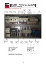
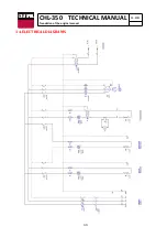
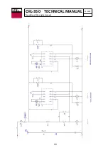
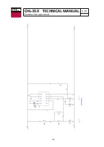
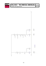
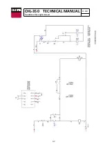
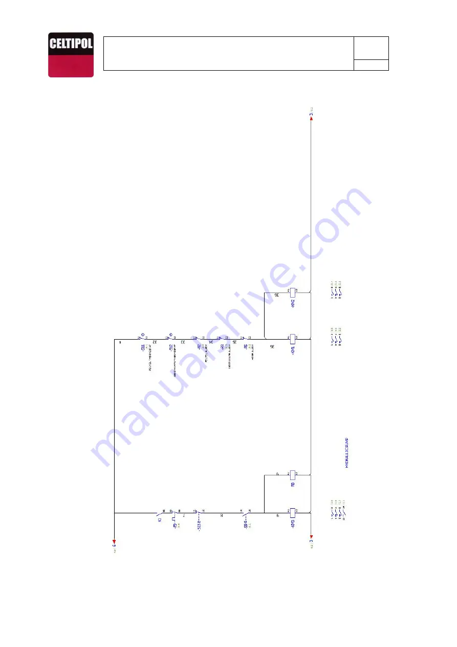
Page 33: ...33 CHL 350 TECHNICAL MANUAL 03 2021 Translation of the original manual 14 ELECTRICAL DIAGRAMS ...

Page 34: ...34 CHL 350 TECHNICAL MANUAL 03 2021 Translation of the original manual ...

Page 35: ...35 CHL 350 TECHNICAL MANUAL 03 2021 Translation of the original manual ...

Page 36: ...36 CHL 350 TECHNICAL MANUAL 03 2021 Translation of the original manual ...

Page 37: ...37 CHL 350 TECHNICAL MANUAL 03 2021 Translation of the original manual ...

Page 38: ...ol h On off POLY ISO heaters i Red pilot excess pr or temp of isocyanate j Isocyanate Thermostat k Red pilot hose excess temperature l Hose thermostat m On off heater hose n Hose ammeter o POLY ISO pump start stop p Start stop hydraulic pump q Isocyanate pressure gauge r Pressure gauge air hose s Hydraulic oil level and thermometer t Hydraulic pump pressure regulator u Hydraulic oil pressure gauge...

Page 39: ... the original manual w x z1 z2 z3 y w Air inlet pressure regulator x Pressure gauge air inlet y Air intake stopcock z1 Isocyanate input connection z2 Polyol input connection z3 Compressed air inlet connection z4 Auxiliary compressed air connections z4 ...

Page 40: ...for bleeding the air in the same 2 11 Put the general switch a in the ON position 12 Connect hydraulic pump by start button p 13 Select the working pressure by means of a pressure regulator t located on the front of the machine A pressure bar must be selected depending on the product to be used It is displayed on the pressure gauge u i Polyurea 170 200 bar ii Polyurethane 100 120 bares In the pres...

Page 41: ...ocking when the machine reaches the end of the cycles indicated This cycle counter e can perform two functions 1 Only count cycles when the machine is not stopped 2 Count cycles and blocking the machine when following the programmed cycles 1 Do not start up the system without material in the pumps or tanks 2 Do not unscrew the loose nut on the gun with the machine in 3 Do not connect the heaters w...

Page 42: ...the stopcock taps on the products in the gut and pull the trigger several times until the pressure in the products decreases below 30 bars see output pressure gages q v 7 Deactivate the pump with the stop pushbutton p 8 Disconnect the main switch a 9 Close the stopcock taps for products on the gun and pull the trigger 2 or 3 times 10 Close the air stopcock on the gun 11 Dismantle the side and fron...

Page 43: ...ers with solvent and then cover with Celtipol grease 9 Clean the large needles in the plug on the material tanks with solvent cover with Celtipol grease reinstall the plugs caps on the drums when received from the material supplier 21 SYSTEM MAINTENANCE Check the condition of the existing DOP plasticizer oil in the lubrification bottle of the Isocyanate pump Empty every two weeks clean with ethyl ...

Page 44: ...e procedure to locate breakdowns is as follows 1 Identify the product missing 2 Check the pressure gage corresponding to the material that is missing q w in such a manner that if the reading is higher than normal there is an obstruction problem between the pressure gage and the point in the chamber where the gun makes the mix Conversely if the reading is lower than normal there is an obstruction p...

Page 45: ...er ball If the flash appears on the ascending run check the seating of the upper ball In any case repair works should be carried out as soon as possible The unit should be open and in contact with the air as brief a time as possible in order to avoid other problems such as incoming humidity in the system or crystallization of the isocyanate In the event of the unit being exposed to the atmosphere ...

Page 46: ...e the main switch a must be set to the ON position lighting up the green LED light b located above the switch If this LED does not light up this indicates that the electrical power does not exist or is faulty 2 Incorrect connection of the phases Check the correct phase connection If the phases are incorrectly connected the phase sequence monitoring relay 9012 prevents the machine from starting Con...

Page 47: ...esult of an obstruction If the pressure is lower decompensation is the result of a problem in the pumping system 6 Cavitation Cavitation occurs when the pumping system requires a greater volume of material than that supplied by the feeding system leading to the formation of a vacuum in the dosing pump The causes that can cause cavitation are as follows a The transfer pump fails to supply the requi...

Page 48: ... occurs The fault can also be seen in the corresponding product gauge Until the pressure falls below the set limit the machine cannot be restarted by resetting the push buttons at the start of each function To do this press the RESET button with the red light d located above the emergency stop and then reset the start buttons of each function h m o p 9 Temperature controllers The machine has a tem...

Page 49: ... is affected by the following parameters Temperature A material that is too hot will produce separation in the fan A material that is too cold will produce a ripple effect Pressure Too high a pressure will result in excessive or disaggregated spraying A pressure that is too low will produce a ripple effect Contamination of the products in the mixing chamber A foreign object in the mixing chamber w...

Page 50: ...1500W resistance p 26 3075 Polyol heater p 26 3076 Tapón 3 4 NPT p 26 3100 C Armaflex thermal coating p 31 3500 Bicolor anti abrasion covering p 31 3503 Motor ventilation grill p 9 3530 Front housing p 9 3531 Isocyanate heater protection p 12 3532 Polyol heater protection p 13 3533 Transformer housing p 9 3534 Back cover p 11 12 3535 Control cabinet p 12 3536 Control cabinet cover p 9 3538 Transfo...

Page 51: ... 2 p 25 7035 M M 1 2 G joint p 18 25 7036 Air pressure gauge Ø51 p 25 7037 Elbow 90º 3 8 quick connector p 25 7039 Solenoid valve p 13 18 7043 Air pressure gauge Ø52 p 9 7044 Hydraulic high pr gage Ø62 p 9 7045 Products high pr gage Ø62 p 9 26 7046 Presostat p 26 7049 Thermometer and hydraulic level p 9 7052 Temperature controller ESM4420 p 10 7053 Start stop button p 10 7054 Ammeter p 10 7055 Mai...

Page 52: ...3 2021 Translation of the original manual 26 TRANSFER PUMPS C M 16 Technical characteristics of the equipment Air pressure 7kg cm Air consumption 200l min Maximum product outlet pressure 20kg cm Pressure ratio 2 8 1 Outflow 30l min ...

Page 53: ... to be stored at all times in suitable containers following the manufacturer s recommendations Containers must not be opened until immediately before being used in order to avoid contamination by damp Any leftover product after being applied should be put back into the original container and be stored in a dry ventilated place During cleaning tasks of spilt components it will be essential to use e...

Page 54: ...nect the product outlet hose 2918 at both ends Connect the air inlet hose 2919 to the pump through the pressure regulator kit 5077 Connect the air hose 2919 to the air outlet The pump will start working when the stopcock 1202 is opened Turn the regulator 7093 until the pressure gauge 1201 reaches a maximum of 7 bar To increase the durability of the equipment it is recommended to treat the air usin...

Page 55: ...CHL 350 TECHNICAL MANUAL 03 2021 Translation of the original manual Kit 5006 Kit 5071 Kit 5072 Kit 5075 Kit 5006 Kit 5071 Kit 5072 Kit 5075 5028 5069 5827 5826 5034 5036 5052 5051 5054 5053 5059 5059 5060 ...

Page 56: ...5002 5003 5049 5047 Kit 5075 5045 5048 5050 5046 5055 5011 5019 5013 5007 5005 Kit 5077 5008 5009 5010 5014 5016 5015 Kit 5006 5027 5025 5024 5056 5057 5058 Kit 5072 Kit 5074 5064 5066 5065 5068 5067 5017 5031 5032 5080 Kit 5071 5035 5043 5041 5042 5044 5005 5001 5030 5029 ...

Page 57: ...5046 Lower piston plate 1 5047 Upper piston plate 1 5048 Stem 1 5049 Piston nut 1 5050 Piston stay bolt 3 5055 Screw M4 3 5056 Upper stem 1 5057 Top stop ring 1 5058 Lower stop ring 1 5064 Fluid separator 1 5065 O ring Øint 40x2 1 5066 Internal cane 1 5067 Lower stem 1 5068 Suction rod 1 5080 Piston ring 1 7019 Joint M 1 2 M 1 1 16 SAE 1 Kit 5071 Lower piston REF DESCRIPTION QT 5034 Piston board 1...

Page 58: ...products with new or recycled products in accordance with the laws of each country Conditions 1 This guarantee is valid only when presented with the original invoice or sales receipt indicating the date of sale and model purchased along with the faulty product CELTIPOL reserves the right not to offer the free guarantee service if these documents are not presented or if the information they contain...

Page 59: ... carried out by a non authorized technical service or by the consumer Accidents lightning water fire inadequate ventilation or any cause beyond the control of CELTIPOL Electronic components inside the control panel affected by bad connections or sudden voltage changes electrical fluid deficiencies Faults of the system to which this product is incorporated This guarantee has no influence whatsoever...

Page 60: ...60 CHL 350 TECHNICAL MANUAL 03 2021 Translation of the original manual 28 CE DECLARATION ...

Page 61: ...61 CHL 350 TECHNICAL MANUAL 03 2021 Translation of the original manual ...

Reviews: