48
CHL-350 TECHNICAL MANUAL
03-2021
Translation of the original manual
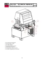
The dosing pump system has two limit switchs ref.(5292 or 5302) to change the
direction of the pumping unit.
If one of them fails, the pump unit will lock in position near where the end of stroke
has failed.
Check:
a. There are no foreign bodies inside the transparent housing that prevent the
contact of the bushing (ref.3585 or 3586) with the limit switches.
b. Manually activate the solenoid valve (ref.7039) to rule out any failure in the
same.
c. Electrical current in the ends of run.
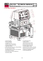
8. Safety pressure switches:
The hydraulic circuit of each product has a factory set safety pressure switch
(ref.7046) at a pressure limit depending on the size of the pumps installed in the
machine.
When the limit pressure is reached, the machine stops running and the red light (
g, i
)
above the temperature controllers lights up. The situation of the red light that lights
indicates where the fault occurs. The fault can also be seen in the corresponding
product gauge.
Until the pressure falls below the set limit, the machine cannot be restarted by
resetting the push-buttons at the start of each function. To do this, press the RESET
button with the red light (
d
) located above the emergency stop, and then reset the
start buttons of each function (
h, m, o, p
).
9. Temperature controllers
The machine has a temperature probe installed in each of the heaters (ref.3056) and
a probe in the hose (ref.7223) that, through their respective controllers on the
control panel (
f, j, l
), can adjust the temperature according to customer requirements.
Each of the temperature controllers (
f, j, l
) has a programmed safety temperature,
which when exceeded stops the operation of the machine.
In addition, an alarm is created in the temperature controller (AO1 in red) and the
red light above the controller where the alarm is created is lit.
Until the temperature drops below the programmed limit, machine operation cannot
be restarted. To do this, press the RESET button with the red light (
d
) located above
the emergency stop, and then reset the start buttons of each function (
h, m, o, p
).
Summary of Contents for CHL-350
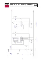
Page 33: ...33 CHL 350 TECHNICAL MANUAL 03 2021 Translation of the original manual 14 ELECTRICAL DIAGRAMS ...
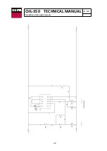
Page 34: ...34 CHL 350 TECHNICAL MANUAL 03 2021 Translation of the original manual ...
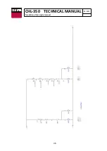
Page 35: ...35 CHL 350 TECHNICAL MANUAL 03 2021 Translation of the original manual ...
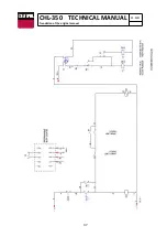
Page 36: ...36 CHL 350 TECHNICAL MANUAL 03 2021 Translation of the original manual ...
Page 37: ...37 CHL 350 TECHNICAL MANUAL 03 2021 Translation of the original manual ...
Page 60: ...60 CHL 350 TECHNICAL MANUAL 03 2021 Translation of the original manual 28 CE DECLARATION ...
Page 61: ...61 CHL 350 TECHNICAL MANUAL 03 2021 Translation of the original manual ...

