background image

58

16

 - 

T

ESTING THE MEASURING HEADS BY FITTING THEM ON THE VEHICLE


16.1 - Measurement I – Toe-in and camber in driving direction 

Position the vehicle in the measuring position but not above the turn plates and the sliding plates. Engage the 

brake pedal lock. Fasten the quick-fastening units. Fit the measuring heads and align them horizontally using 

a spirit level. Measure the total toe-in on the front and rear wheels based on the measurement sheet (rows 

1-2) and note down the values in column 1. Measure the camber on the front and rear wheels based on the 

measurement sheet (rows 3-6) and note down the values in column 1.


16.2 - Measurement II - Toe-in and camber in reverse driving direction

Exchange the front left measuring head with the rear right measuring head, and the front right measuring 

head with the rear left measuring head, then horizontally align all the measuring heads using a spirit level 

taking care not to move the vehicle. Measure the total toe-in on the front and rear wheels based on the mea-

surement sheet (rows 1-2) and note down the values in column 2. Measure the camber on the front and rear 

wheels based on the measurement sheet (rows 3-6) and note down the values in column 2.


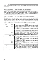
16.3 - Evaluation of the values measured during the measuring head test

Column

Row

Operation

1 and 2

1-2

If there are different signs in the same row, subtract the smaller from the 

larger value and note down the result in column 3. Note down the larger 

value sign in column 3
If the signs are the same, add the measurement values and note down the 

result with the sign in column 3

3-6

If there are different signs in the same row, add the values and note down 

the results in column 3. Note down the sign of column 1 in column 3.

If the signs are the same, subtract the smaller from the larger value and 

note down the result in column 3. If the larger value is in column 1, the 

sign is accepted; if the larger value is in column 2, the sign is changed

Values to compare:

3

1 with 2

If the signs are different, add the measurement values and note down the 

result in column 4
If the signs are the same, subtract the smaller from the larger value and 

note down the result in column 4

3 with 6

4 with 5

If the signs are different, subtract the smaller from the larger value and 

note down the result in column 4

If the signs are the same, add the measurement values and note down the 

results in column 4

4

The values in column 4 must be smaller than 3'. If they are larger, it 

means that errors occurred during the measurement (e.g. the vehicle or 

the quick-fastening units moved) and the measurement must be repeated

3

The values in column 3 must be smaller than 15'. If the differences are 

greater, the device must be recalibrated (Technical Service)

Summary of Contents for DWA1100

Page 1: ...o 9 23826 Mandello del Lario LC ITALY Telefono 39 706369 Fax 39 0341 700725 www cemb com garage cemb com The Manufacturer declines all liability for any damage to people or property caused by incorrec...

Page 2: ...ruzioni originali Translation of the original instructions Traduction de la notice originale bersetzung der Originalanweisungen Traducci n de las instrucciones originales Tradu o das instru es origina...

Page 3: ...IT AND ALIGN THE BAR ON THE FIFTH WHEEL PIN 25 6 RUNOUT 26 6 1 HOW TO EXECUTE RUNOUT 28 6 2 180 OR 90 RUNOUT ON THE GROUND 29 6 3 180 RUNOUT LIFTED 31 6 4 3X90 RUNOUT LIFTED 32 7 STEERING 33 7 1 FAST...

Page 4: ...T PROBLEMS 55 15 STORING AND SCRAPPING 57 15 1 STORING 57 15 2 SCRAPPING 57 16 TESTING THE MEASURING HEADS BY FITTING THEM ON THE VEHICLE 58 16 1 MEASUREMENT I TOE IN AND CAMBER IN DRIVING DIRECTION 5...

Page 5: ...trician Do not modify or improperly use the plug This machine is not equipped with a manual power cutting device To cut the power pull out the plug or turn off the main switch positioned upstream All...

Page 6: ...4...

Page 7: ...rtical angles The power is supplied by rechargeable batteries when the batteries are flat measurements can still be made by connecting the battery charge cables supplied as option and not included in...

Page 8: ...pedal lock This device is used to lock the brake pedal while preparing to make a measurement 1 Handle 2 Off 3 Plate with non slip disc 4 Goniometer 5 Reference dial Steering lock This device is used t...

Page 9: ...time 60 minutes Red battery flat estimated operating time 30 minutes Grey no communication Black rear measuring head not used in the 2 measuring heads mode 1 1 Battery and communication status On some...

Page 10: ...dity of the battery warranty Recharge the batteries at least once every 6 months a partial recharge 50 is sufficient Operate in a temperature range between 0 and 45 C Precautions for use of the batter...

Page 11: ...MENT VEHICLE SELECTION VEHICLE SPECIFICATIONS RUNOUT STEERING 2 PROGRAM FLOW AXLE SELECTION Chapter 10 DIAGNOSTICS Chapter 11 ADJUSTMENT Chapter 12 SUMMARY The following flow chart schematizes the typ...

Page 12: ...buttons of the measuring head keypad On the normal pages the function of these keys varies from page to page or goes back to the previous page or goes to the next page help goes back to the home page...

Page 13: ...ter because you do not have to fit the rear measuring heads It is recommended that only experts use the mode with 2 measuring heads as it is not guaranteed that the steering wheel stays straight Gener...

Page 14: ...er databank page test calibration goes directly to measurement without selecting the vehicle If the databank activation window appears on the home page the databank must be activated 13 2 Nevertheless...

Page 15: ...ground UP lifted only Bypass runout execution not required 10 Enables checks on correct runout execution 11 Help texts OFF disabled ON displays on the screen buttons their name ON INF displays the pre...

Page 16: ...Print settings 1 Logo ON OFF 2 Colour in which out of tolerance values are printed measurements before and after adjustment red measurements before and after adjustment black only measurements after...

Page 17: ...measurements before and after adjustment How to set it Create a new folder where wished to save the data Any accessible path in the network can be used Enter the SET UP page and select the DATA EXPOR...

Page 18: ...x deletes the customer vehicle selected backup see below restore see below selects the search box or the customer list select the desired customer displays the customer measurements of the selected cu...

Page 19: ...ered as of the year indicated You can also insert informations on a customer which are saved in the customer databank together with the summary of the measurements so that they can be viewed and print...

Page 20: ...18 saves the informations and exits 4 2 Customer informations Press to insert customer informations...

Page 21: ...orrectly display the toe in in millimetres or inches and custo mise the vehicle specifications 1 Wheelbase and track Axles to which the specifications refer 2 Vehicle make model sub model or technical...

Page 22: ...t help images Selecting this option a page is displayed showing the images of the mechanical adjustments that can be made on the vehicle being measured displays the next image goes back to the Vehicle...

Page 23: ...e tools have been applied and the measurements made consult the tables If they indicate that you need to check that the measurement is within a certain tolerance interval and this is not the case act...

Page 24: ...ications page 5 4 Vehicle customisation To access this page press then from the Vehicle Specifications page The Vehicle Customisation page allows adding vehicles to the vehicle database To do this fir...

Page 25: ...ghts and percentage fuel in the tank selects the unit of measure and the format of the data to be entered for the angles 60 sexagesimal degrees e g 1 55 100 centesimal degrees e g 1 55 min std max dat...

Page 26: ...ble to adjust the thrust angle for any axle select the one where the tyres are less worn as they will be better aligned with the fifth wheel pin compared to the other axles 2 Non steering axle to prev...

Page 27: ...e you are asked to fit the front measuring heads on the fifth wheel pin adaptor 1 Position the bar on the pin and tighten the fastening knob 2 Fit and level the two front sensors on the bar 3 Straight...

Page 28: ...d Fast Like the 180 runout on the ground this method is fast and does not alter the suspension settlement The requirements are identical except that this method can also be used with shorter surfaces...

Page 29: ...n the ground Are there often wheel steering errors during movement when exe cuting the runout methods on the ground 180 LIFTED Is the car lift long enough for the 180 runout on the ground 90 ON THE GR...

Page 30: ...e orange arrows and the rear measuring heads where indicated by the blue arrows 4 Follow the instructions in the following paragraphs according to the runout method selected 5 Position the brake pedal...

Page 31: ...turn 90 4 Level the measuring heads and press 5 Push the vehicle forwards until it is back in the starting position 6 Level the measuring heads lock the handles and press 7 Release the front turn plat...

Page 32: ...nd in CAR measuring mode before moving the vehicle step 3 position the rear sensors type TRUCK in the following position Fasten the rear sensors by tightening the pin locking knob that way you prevent...

Page 33: ...y half a turn 180 so that the knob of the wheel clamp faces up level the mea suring head and press 5 Repeat steps 3 and 4 for the other wheels 6 Release the front turn plates and the rear slip plates...

Page 34: ...ront turn plates and the rear slip plates 7 Lower the vehicle 8 Settle the suspension by forcefully pushing on the vehicle so that it oscillates Pay attention to the direction of rotation of the wheel...

Page 35: ...g recommended because it is fast to execute 10 steering there is no technical reasons to use this method but it is available because many operators are accostumed to use it It is advisable to execute...

Page 36: ...in 6 Without moving the steering wheel wait a few seconds The vehicle Diagnostics page appears 8 7 2 10 or 20 steering 1 Steer in the direction indicated by the arrow until aligning the triangles the...

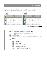
Page 37: ...on the vehicle before adjustment next to the data bank specifications The measurements out of tolerance are displayed in red so that you can easily identify what to adjust displays the vehicle dimens...

Page 38: ...a green and red scale Adjust the angles until the indicator is in the green zone representing the angles in tolerance while the red zone represents the angles out of tolerance To make it easier to see...

Page 39: ...termediate axles 4 If necessary adjustment of the last rear steering axle only if present 5 If necessary adjustment of the parallelism between the two front steering axles only if present Semi trailer...

Page 40: ...play from partial toe in to total toe in or shows the front and rear axle simultaneously 9 3 9 3 Adjusting a front axle Before adjustment of a front axle the following may appear 1 Level the steering...

Page 41: ...of the total toe in and the steering angle allows adjusting vehicles equipped with a total toe in adjustment bar which does not allow adjusting the two wheels independently this is true for all trucks...

Page 42: ...eering box 3 Lock the steering wheel with the steering lock 4 Adjust underneath the vehicle to bring the total toe in into tolerance and the steering angle to null To make it easier to identify the ad...

Page 43: ...with respect to the chassis and the truck will thus move in dog step with the consequent aerodynamic problem It is advisable to adjust the distance between the wheels and the chassis at least for the...

Page 44: ...the adjustment procedure you are asked to position the four measuring heads on the two front steering axles to adjust the parallelism between the direction of the first and the second front steering a...

Page 45: ...do some checks on the vehicle 1 Check the vehicle conditions If they do not fall within one of the cases contemplated in the message press to go directly to the Front Adjustment page otherwise press t...

Page 46: ...cedure consists of storing freezing the measurements with the vehicle lowered and the wheels straight in order to keep them unaltered also after the vehicle has been lifted or the wheels steered Thus...

Page 47: ...evel the steering wheel and position the steering lock before lifting the vehicle 9 8 Adjustment in case of interruption of the infrared rays If you are unable to adjust without standing between the o...

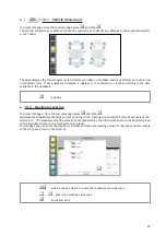
Page 48: ...from the Customer Databank page 3 3 menu runout 6 steering 7 customer informations 4 2 maximum steering 10 2 vehicle dimensions 10 1 Once you have completed the adjustments the Summary page appears su...

Page 49: ...in the databank printing 10 2 Maximum steering To access this page from the Summary page press and then Maximum steering allows checking correct centring of the steering box and all the directional de...

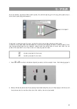
Page 50: ...Steer in the direction indicated by the arrow until the word STOP appears to align the wheels 2 Level the measuring heads of which the level indicators are shown on the display until they are in hori...

Page 51: ...incli ning the measuring heads that are unable to measure until the optical sensors can see each other You can activate this procedure for the front or the rear measuring heads or both spoiler proced...

Page 52: ...the measuring head on the other side of the vehicle right front until only the central green LED is shown on then lock the handle Both the measuring heads are now at the same level and the optical sen...

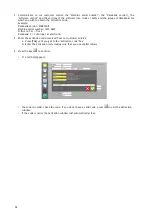
Page 53: ...ow to activate the databank and the software When to perform it After updating the databank for which you do not have access rights on the home page the activation window appears and the message Inval...

Page 54: ...erial number 1234 003F Software Car Truck Databank 1 4 Europe car and truck 3 Enter the activation code received from our customer service a Press TAB until you get to the Activation code box b Enter...

Page 55: ...connections Press the battery recharge button 1 2 The battery life is too short Low ambient temperature Normal phenomenon Recharging not complete Recharge the batteries for at least 5 hours The batte...

Page 56: ...om the computer Check that the mouse is connected to the computer The printer does not work The printer is off Turn on the printer by pressing the button on the printer Printer disconnected from the c...

Page 57: ...heads Steering wheel not aligned when requested Repeat the measurement aligning the steering wheel when requested Approximate adjustment of the alignment angles Repeat the measurement adjusting the a...

Page 58: ...icle getting in the way Activate the Spoiler procedure 12 CCD sensor blinded by the sun Put the CCD sensor in the shade On the road the vehicle pulls to one side Tyres differently worn Replace the tyr...

Page 59: ...is no longer to be used it must be made inoperational Render harmless any parts which may constitute a source of danger Assess the machine classification according to the degree of disposal Take scrap...

Page 60: ...est Column Row Operation 1 and 2 1 2 If there are different signs in the same row subtract the smaller from the larger value and note down the result in column 3 Note down the larger value sign in col...

Page 61: ...ent value IN REVERSE DRIVING DIRECTION S i g n M e a s u rement value S i g n Difference TOE IN TOE IN 1 Total front toe in _ 3 Total rear toe in 5 2 2 Total rear toe in 30 Total front toe in _ 27 3 C...

Page 62: ......

Reviews: