background image

47

93+63(('

Summary of Contents for SM645

Page 1: ...montiergerat Ed 02 16 Manuale di installazione uso e manutenzione lstruzioni originali Installation operation and maintenance guide Original instructions Manuel d installation d utilisation et d entretien Instructions originales Installation bedienung und wartung Originalbetriebsanleitung SM645 ...

Page 2: ...enze generali per Pag 38 la manutenzione 12 TABELLA GUASTI RIMEDI Pag 43 13 DATI TECNICI Pag 45 14 SCHEMI ELETTRICI E PNEUMATICI Pag 46 INTRODUCTION Pag 7 1 DESCRIPTION OF THE MACHINE Pag 9 Danger and prohibition warning signs Pag 10 2 GENERAL Pag 11 2 1 Intended use Pag 11 2 2 General safety precautions Pag 12 3 TRANSPORT Pag 13 4 UNPACKING Pag 13 5 INSTALLATION Pag 14 5 1 Space required Pag 14 5...

Page 3: ...S FONCT CAUSES REMEDES Pag 43 13 DONNÉS TECHNIQUES Pag 45 14 SCHEMAS ELECTR ET PNEUM Pag 46 EINFÜHRUNG Seite 7 1 BESCHREIBUNG DER MASCHINE Seite 9 Gefahrenhimweise und Verbote Seite10 2 ALLGEMEINES Seite11 2 1 Verwendugszweck Seite11 2 2 Allgemeine Sicherheitsvorschriften Seite12 3 TRANSPORT Seite13 4 AUSPACKEN DER MASCHINE Seite13 5 INSTALLATION Seite14 5 1 Platzbedarf Seite14 5 2 Bestandteilenei...

Page 4: ... n a a ...

Page 5: ...gen denn sie enthalten wichtige Hinweise zur Betriebssicherheit und Wartung Conservare con cura questo manuale per ogni ulteriore consultazione Keep this manual for further reference Conserver très soigneusement ce manuel pour le consulter si nécessaire Bewahren Sie dieses Handbuch sorgfältig auf damit Sie es jederzeit wieder konsultieren können Anm ein Teil der in diesem Buch enthaltenen Abbildun...

Page 6: ...tton G Mors de blocage I Tête de montage M Barre de montage N Bras horizontal P Bras vertical Q Raccord air comprimé R Détalonneur S Supports de roue T Levier démonte pneus U Pédale de commande du détalonneur V Pédale de commande des mors Z Pédale de commande de l inverseur H Pédale de commande de basculement du bras Y Plateau à centrage automatique K Poignée de blocage G Spannklauen I Montierfuß ...

Page 7: ...10 AVVERTENZE DI PERICOLO DANGER WARNING SIGNS AVIS DE DANg ER GEFAHRENHINWEISE ...

Page 8: ... 4XHVWR VPRQWDJRPPH DXWRPDWLFR q VWDWR SURJHWWDWR H UHDOL DWR HVFOXVLYDPHQWH SHU OR VPRQWDJJLR H LO PRQWDJJLR GHL SQHXPDWLFL GDL VXL FHUFKL FRQ GLPHQVLRQL GD 2 D 6 H GLDPHWUR PD 2 2 6 2 2 6 2 2 6 2 ...

Page 9: ... 10 10 10 10 ...
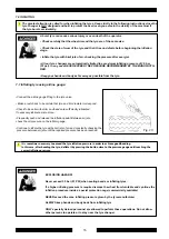
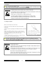
Page 10: ...ur mit einem dazu geeigneten Gabelstapler angehoben und transportiert werden wobei die Gabeln an den in Abb 3 angegebenen Punkten einzuschie ben sind 4 DISIMBALLO Togliere il cartone di protezione e il sacchetto in nylon Assicurarsi dell integrità dell apparecchio controllando che non vi siano parti visibilmente danneggiate o In caso di dubbio non utilizzare la macchina e rivolgersi al proprio riv...

Page 11: ...DFKLQH WR RSHUDWH FRUUHFWO DQG ZLWKRXW DQ UHVWULFWLRQ I WKH PDFKLQH LV LQVWDOOHG RXWVLGH LW PXVW EH SURWHFWHG E D OHDQ WR 7KH VHPL DXWRPDWLF W UH FKDQJHU PXVW EH FRQQHFWHG WR WKH PDLQV HOHFWULF SRZHU VXSSO DQG WKH 7 7 W LV WKHUHIRUH DGYLVDEOH WR LQVWDOO WKH PDFKLQH QHDU WKHVH SRZHU VRXUFHV 7KH SODFH RI LQVWDOODWLRQ PXVW DOVR SURYLGH DW OHDVW WKH VSDFH VKRZQ LQ SLFWXUHV VR DV WR DOO 7 7 WR RSHUDWH ...

Page 12: ... 5K NG FÃOQPVG RPGWU GUV FW V RG OQVGWT ÃNGEVTKSWG UQP WVKNKUCVKQP GUV KPVGTFKVG RTÂU FG OCVKÂTGU GZRNQUKXGU OQKPU SWŏKN PG UŏCIKUUG FŏWPG XGTUKQP CRRTQRTKÃG ...

Page 13: ...nel 5 2 MONTAGE DES COMPOSANTS Après avoir déballé et positionné la machine il est nécessaire de retirer les blocages du bras vertical pour le libérer L emballage principal contient deux autres emballages l un contient les accessoires et l autre le porte objets Positionner le levier lève talons dans son logement et l anneau de soutien du réservoir de graisse dans les deux trous prévus sur le flanc...

Page 14: ... side corner using the standard screws provided Refit the left hand side panel 5 2 1 Montage du porte objets Sortir le porte objets de son emballage Retirer le flanc gauche du démonte pneu en dévissant les quatre vis Installer le porte objets sur l angle du flanc gauche en utilisant les vis fournies à cet effet Remonter le flanc gauche 5 2 1 Montage der Ablagekonsole Die Ablagekonsole aus der Verp...

Page 15: ...18 ...

Page 16: ...19 7 67 81 21 0 172 1 pedale posto sul lato sinistro the inflating pedal located on the left side SRV SRV ...

Page 17: ...20 la pédale de gonflage placée sur le côté gauche Auf Druck des Pedals an der linken Gehäuseseite tritt Luft aus dem Scherkopf SRV SRV ...

Page 18: ...1 1RWH VXOO XWLOL R 93Y005101 93Y005101 93Y005101 93Y005101 ...

Page 19: ... 2 t ...

Page 20: ... 3 ...

Page 21: ...palmare il grasso in dotazione o grasso di tipo simile sui talloni del pneumatico Durante l operazione di ribaltamento del palo accertarsi che nessuno sosti dietro lo smontagomme Assicurarsi che il cerchio sia ben agganciato alle griffe Richiamare il palo P premendo il pedale H Sbloccare il braccio operante M ponendo il pulsante di bloccaggio K in pos 2 sul bordo superiore del cerchio e bloccare i...

Page 22: ...e pedal H Unlock the mounting bar M by placing the locking button K into position 2 Lower the mounting bar M so that the mounting head I rests against the upper edge of the wheel rim and lock the entire assembly by placing the locking button into position 1 This will lock the arm in both vertical and horizontal direction and automatically move the mounting head I of about 2 mm from the rim With th...

Page 23: ...26 s assurer que le pneumatique est détalonné l élément coulissant ...

Page 24: ... 7 0217 Vor jedem Vorgang sicherstellen dass der Reifen abgezogen worden ist HL UPNLSSHQ VROO QLHPDQG KLQWHU GHU 0DVFKLQH VLFK EH QGHQ an der Gleitstange ...

Page 25: ...28 ...

Page 26: ...29 ...

Page 27: ...30 ...

Page 28: ... 1 ...

Page 29: ...remere e rilasciare con frequenza il pedale di gonfiaggio controllando del pneumatico sul cerchio Fig 20 PERICOLO DI ESPLOSIONE Non superare mai la pressione consigliata dal costruttore e comunque i 3 5 bar 51 PSI a cui la macchina è auto limitata Quando fosse richiesta una pressione di esercizio del pneumatico superiore togliere la ruota te reperibili sul mercato Mantenere mani e corpo il piu lon...

Page 30: ...pedal It is sometimes necessary to exceed the tyre inflation pressure in order to achieve good beading In this case after beading the tyre deflate it by pressing the button close to the pressure gauge until reaching the correct inflation pressure ...

Page 31: ...obtenir un bon talonnage il est parfois nécessaire de dépasser la pression de gonflage du pneumatique Dans ce cas après avoir talonné le pneumatique le dégonfler en appuyant sur la touche située près du manomètre jusqu à ce que la bonne pression de gonflage soit atteinte ...

Page 32: ...anchmal ist es zum vollständigen und korrekten Aufziehen des Reifens erforderlich den vorgeschriebenen Reifendruck zu überschreiten In diesem Fall nach dem Aufziehen des Reifens die Luft durch Betätigen der Taste am Manometer wieder ablassen bis der vorschriftsmäßige Reifendruck erreicht ist ...

Page 33: ...36 ...

Page 34: ...37 ...

Page 35: ...38 l ...

Page 36: ...39 ...

Page 37: ...40 ORDINARIA 1 ROUTINE 1 ...

Page 38: ...41 ORDINAIRE 1 ROUTINE 1 ...

Page 39: ...42 ...

Page 40: ...43 ...

Page 41: ...44 ª ª ª ª ...

Page 42: ...45 13 DATI TECNICI TECHNICAL DATA DONNEES TECHNIQUES TECHNISCHE DATEN 12 26 380 mm 15 100 mm 477 0 75 1 125 Kw 5120x1580x2100 335 Kg 1200 mm 47 356 mm 14 335 Kg 1560x1720x1998 0 75 1 125 kw ...

Page 43: ...46 6 0 775 31 80 7 75 1 31 80 5 06 6 0 6 75 48 7 31 80 7 48 6 7 81 58 8 7 3 b1 6 0 775 31 80 7 75 1 31 80 5 06 6 0 6 75 48 7 31 80 7 48 6 7 81 58 8 7 3 b1 ...

Page 44: ...47 9 3 63 ...

Page 45: ...inder 7 Wulstabdrückerventil 8 Zentriertischventil 9 Drehanschluß 10 Schmierer 11 Druckregler 12 Lufteinlaß 13 Sicherheitsventil 14 Druckregler 15 Armumkippventil 16 Armumkippzylinder 17 Ventil für die Freigabe Ein spannung des Armes 18 Zylinder für die Freigabe Einspannung des Armes 19 Ventil für die Einspannung des Bedienungsarmes 20 Bedienungsarm Hubzylin der 1 2 Silencieux 1 4 3 Silencieux 1 8...

Page 46: ...ety valve 9 10 Divider 11 Pressure gauge 12 13 14 Rotating union 6 GT Pedalventil 7 Druckregler 8 Sicherheitsventil 9 Aufpumpknopf 10 Verteiler 11 Manometer 12 Aufpumpenaggregat 13 Luftablaßventil 14 Drehanschluß 6 Soupape pédale GT 7 Régulateur de pression 8 Soupape de sécurité 9 10 Repartiteur 11 Manomètre 12 13 14 Raccord pivotant ...

Page 47: ...50 ...

Page 48: ... ...

Reviews: