

7
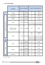
2.2) Setting
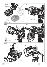
Insert the conductor between the blades, up to the desired cutting point (Ref. to Fig. 2).
To cut short pieces of steel or ACSR ropes, it is suggested to tie or wrap rope with adhesive or
duct tape around the area to be cut and at its end (Ref. to Fig. 2), so to limit the projection of
steel fragments which could damage or hurt the operator.
For a running conductor, remove the locking pin (4) and open the tool head.
Fully retract the lower blade (3) before attempting to open the tool head (Ref. to § 2.6).
With the conductor on the lower blade (3), close the tool head and fully insert the locking pin (4)
(Ref. to Fig. 3).
Before commencing the cutting operation ensure that the pin (4) is fully secured: partial
closure may damage the tool head.
2.3) Blade advancement
Operate the push-button (5) (Ref. to Fig. 2) to activate the motor-pump, the ram will gradually
move forward until the lower blade (3) touches the conductor.
To halt the advancement, release the push-button (6) and the motor will cut out.
Make sure the blade is exactly positioned on the desired cutting point otherwise re-open the
blade following instructions as per § 2.6 and reposition it.
2.4) Cutting
Firmly hold the tool and operate the push-button (5) to gradually move the lower blade (3) to
cut through the conductor.
When the cut is performed, release the push-button (5), otherwise after the maximum pressure
relief valve has activated the motor will stop automatically.
2.5) LED Worklights
Whilst the tool is in operation, the work area is illuminated by two high luminosity LED Worklights
that switch off automatically at the end of the cycle.
2.6) Blade retraction
By operating the pressure release button (6), the ram will retract and open the blades.
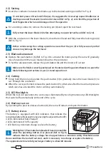
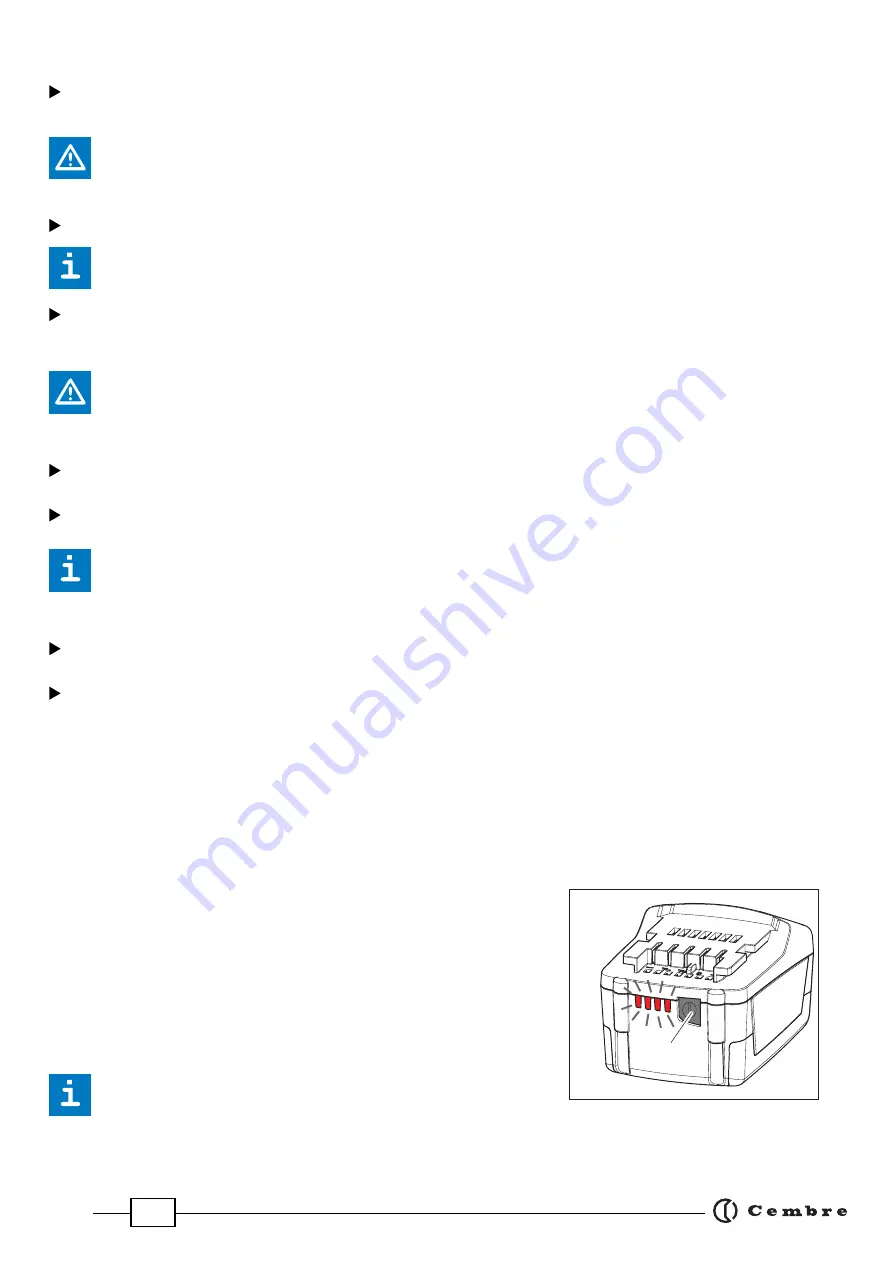
2.7) Battery status
The battery is equipped with LED indicators that indicate the
remaining battery life at any time by pressing the adjacent button (P):
4 LEDs illuminated: fully charged
2 LEDs illuminated: 50 % capacity
1 LED flashing: minimum charge, replace the battery
Worklights (1) illuminated combined with an alarm audible
when the operating button (5) is pressed (Ref. to Fig. 6),
indicate that the battery voltage has dropped below a minimum safety threshold; under
these conditions the tool will not start, and it is necessary to recharge or replace the battery.
The approximate time to fully recharge a battery is about 80 minutes.
P
Summary of Contents for B-TC450A
Page 11: ...11...


