


8
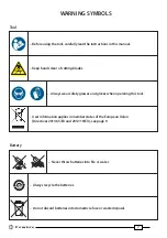
2.8) Using the battery charger
Carefully follow the instructions in the battery charger user manual.
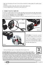
3. MAINTENANCE
The tool is robust, completely sealed, and requires very little daily maintenance. Compliance with
the following points, should help to maintain its optimum performance:
3.1) Thorough cleaning
Dust, sand and dirt are a danger for any hydraulic device. Every day, after use, the tool must be
wiped with a clean cloth taking care to remove any residue, especially close to pivots and move-
able
parts.
Do not use hydrocarbons to clean the rubber parts.
Regularly lubricate the moving parts and pivot pins of the head with a few drops of oil.
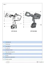
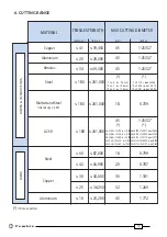
3.2) Storage case
When not in use, the tool should be stored and transported in the plastic case, to prevent dama-
ge. The case, type VAL-P40, is suitable for storing the tool and accessories.
VAL-P40: Size 520x432x126 mm (20.5x17.0x5.0 inches). Weight 2,6 kg (5.7 lbs).
3.3) Routine maintenance
When the tool reaches the predetermined number of hours worked, it will signal that routine
maintenance is recommended.
The tool will continue to work however 15 sec. after use an alarm comprising 3 beeps com-
bined with illumination of the worklights will signal that its return to
Cembre
for service
is recommended (see § 6).
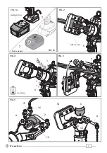
4. BLADE REPLACEMENT
(Ref. to Fig. 5)
When changing blades, the battery must fi rst be removed from the tool.
After extended use, the blades may break or loose their cutting edge.
Replace the blades as follows:
Lower blade
– Release latch (4), and open the tool head completely.
– Operate the tool to advance the lower blade (3) and remove the battery.
– Eject two split pins (12) from the ram (13) to release the blade (3).
– Remove the broken blade from the ram, insert the new blade and fi t with two split pins.
Before closing the tool head, push the release button (6) and fully retract the lower blade,
otherwise the tool head assembly may hit and damage, the lower blade.
Upper blade
– With the lower blade (3) fully retracted, the tool head closed and the locking pin (4) fully secured,
hold the head by the blade spacer (15) in a bench vice with screws (16) facing upwords.
Summary of Contents for B-TC450A
Page 11: ...11...


