background image

9

FIG. 6

99

3

100

101

2

98

99

37

13

1

97

103

102

38

98

18

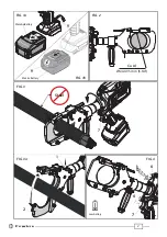
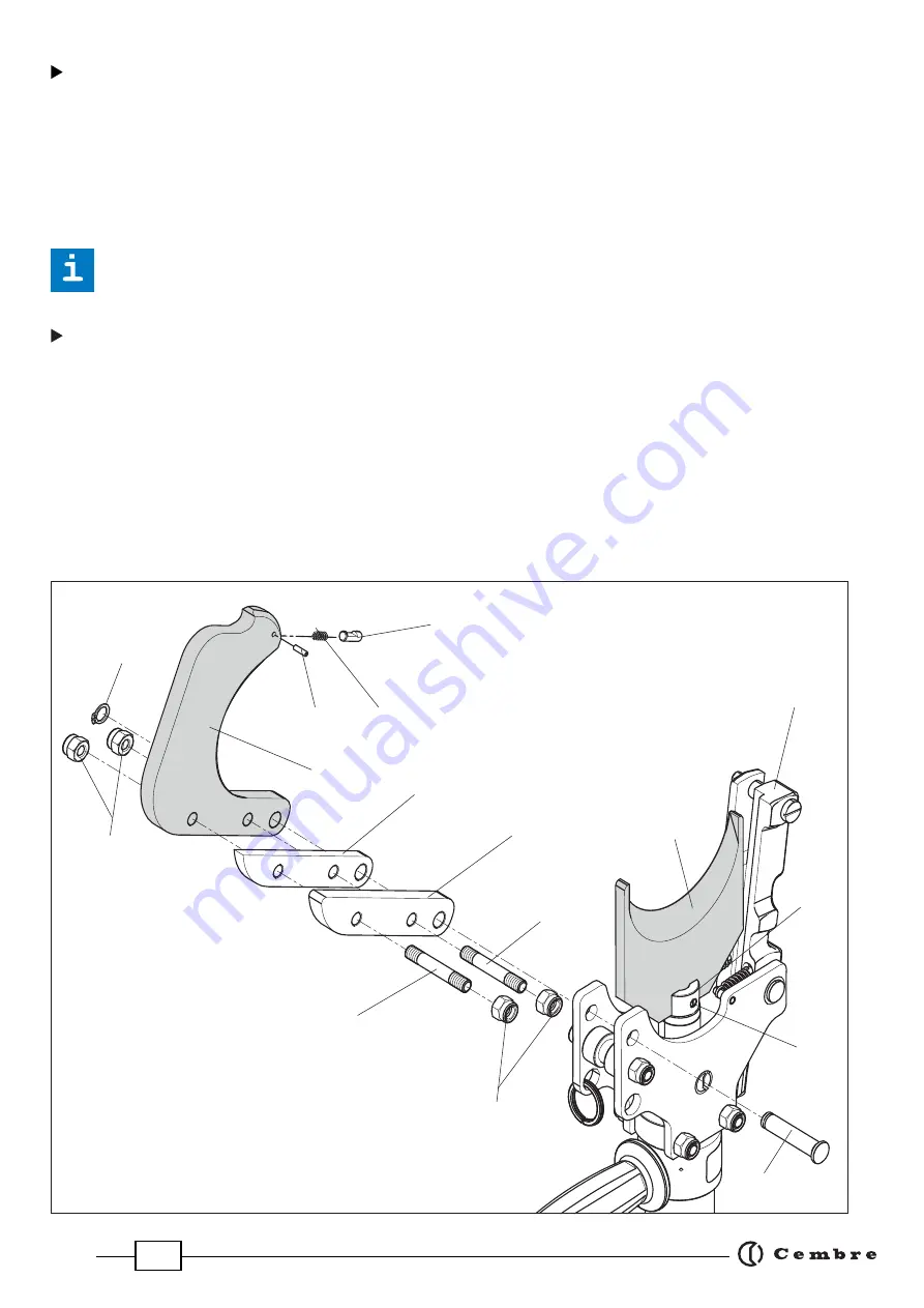
 Lower blade

–  Press lever (1) and open upper blade assembly.

–  Operate tool to advance the lower blade (3) until holding screw (18) is visible on the ram (13), 

  than remove the battery from the tool.

–  Using a fl at blade screwdriver remove the holding screw (18) and release the lower blade (3).

–  Insert the new blade and fi t the holding screw.


Before closing the tool head, release the oil pressure and retract the lower blade, otherwise 

        the tool head assembly may hit and damage the lower blade. 

 Upper blade

–  Press lever (1) and open upper blade assembly.

–  Remove circlip (38) and pin (37).

–  With a 13 mm spanner, undo M8 nuts (98) and remove two studs (99), blade guide (100) blade 

  spacer (101) and upper blade (2), noting the order of assembly.    

–  With a punch, drive out the split pin (102), collecting the spring (103) and the pin (97).

–  Assemble the spring (103) and the pin (97) on the new blade, locking the whole by the split pin

 (102).

–  Fitting the new blade is a reversal of the above.

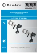
Summary of Contents for B-TC950A

Page 1: ...1 OPERATION AND MAINTENANCE MANUAL 17 M 217 U BATTERY OPERATED HYDRAULIC CUTTING TOOL ENGLISH B TC950A B TC950NA...

Page 2: ...2 FIG 1b Steel Low battery 7 7 FIG 3 6 6 1 2 FIG 3a FIG 4 FIG 2 Cu Al MAX 95 mm 3 3 4 FIG 1a 9 MakitaBattery Metabo Battery 9...

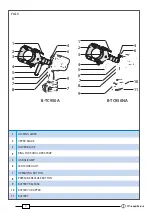
Page 3: ...WER BLADE 4 RING FOR SHOULDER STRAP 5 HANDLE GRIP 6 LED WORKLIGHT 7 OPERATING BUTTON 8 PRESSURE RELEASE BUTTON 9 BATTERY RELEASE 10 BATTERY ADAPTER 11 BATTERY FIG 5 7 8 2 1 6 4 3 4 10 9 11 6 5 6 7 8 2...

Page 4: ...s and gloves when operating this tool WARNING SYMBOLS User information applies in member states of the European Union Directives 2011 65 EU and 2012 19 EU see page 10 Battery Tool Do not cut Steel Nev...

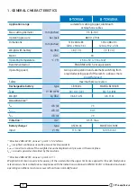
Page 5: ...ation range suitable for cutting Copper Aluminium or telephone cables Max cutting diameter mm inches 95 3 3 4 Operating pressure bar psi 880 12 700 Dimensions mm inches 518 x 468 x 83 20 4 x 18 4 x 3...

Page 6: ...ors The tool is unsuitable for continuous use and should be allowed to cool down following uninter rupted successive cutting operations for instance having exhausted a fully charged battery in one ses...

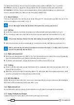
Page 7: ...de 3 close the tool head and fully secure the lever 1 Before commencing the cutting operation ensure that the lever 1 is fully secured partial closure may damage the tool head 2 3 Blade advancement Pr...

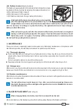
Page 8: ...ery little daily maintenance Compliance with the following points should help to maintain its optimum performance 3 1 Thorough cleaning Dust sand and dirt are a danger for any hydraulic device Every d...

Page 9: ...ng the tool head release the oil pressure and retract the lower blade otherwise the tool head assembly may hit and damage the lower blade Upper blade Press lever 1 and open upper blade assembly Remove...

Page 10: ...ccordance with Directives 2011 65 EU and 2012 19 EU The Notinthebin symbolabovewhenshownonequipmentorpackagingmeansthat theequipmentmust attheendofitslife bedisposedofseparatelyfromotherwaste The sepa...

Page 11: ...11...

Page 12: ...S a r l 22 Avenue Ferdinand de Lesseps 91420 Morangis France T l 01 60 49 11 90 Fax 01 60 49 29 10 CS 92014 91423 Morangis C dex E mail info cembre fr www cembre fr Cembre Espa a S L U Calle Verano 6...

Reviews: