background image

6

ENGLISH

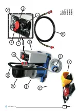
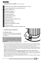
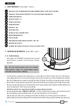
2.   PUMP DESCRIPTION  

(Ref. to Fig. 1, page 3)


SOCKET


FOR


CONNECTING


THE


REMOTE


HAND

 / 

FOOT


PEDAL


CONTROLLER


MAINS


CABLE

 (

PLUG


2


PHASES

 + 

EARTH

)


PROTECTION


FUSES


ON

-

OFF


SWITCH


I


O


QUICK


RELEASE


FEMALE


HYDRAULIC


COUPLER


TRANSPORT


HANDLE


ALARM


LED


ELECTRIC


MOTOR


HYDRAULIC


PUMP

 / 

OIL


RESERVOIR


REMOTE


HAND


CONTROLLER


REMOTE


FOOT


PEDAL


CONTROLLER


OIL


RELEASE

 / 

EMERGENCY


BUTTON


ELECTRICAL


PANEL


3


METRE

 (

9.8


ft

HIGH


PRESSURE


FLEXIBLE


HOSE

3.   INSTRUCTION FOR USE 

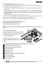
3.1) Setting up 

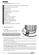
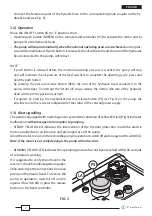
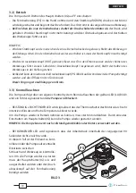
–  Carry the pump using the handle (IM) and place 

  on a fl at, stable surface in a dry position. 

  B

EFORE


OPERATING


THE


PUMP


FOR


THE


FIRST


TIME

REPLACE


THE


TRANSPORT


CAP


WITH


THE


WORKING


CAP


SUPPLIED

.

–  To avoid oil leakage during transportation, the

  pump is equipped with an hermetically sealed cap which must be replaced with the working cap 

  supplied, for correct operation.

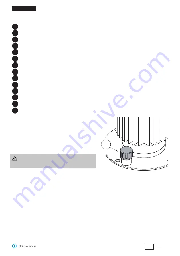
–  Remove the transport cap and replace it with the orange working cap (TL) complete with dipstick 

  for oil level verifi cation, tighten fi rmly.

–  Check that the nominal supply voltage corresponds to the value shown on the pump label then 

  connect to the mains: ON-OFF switch (IG) will light, indicating connection to mains elettricity.


The pump must only be connected to correctly earthed sockets.

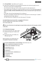
– Remove “

REMOTE CONTROL

” protective cap, connect the remote hand controller to the socket 

  (C) (see Fig. 4 page 35): tighten the plug (CP) by turning the bezel (G) clockwise until it locks. 

–  Connect the fl exible hose (TF) to the hydraulic head and to the corresponding female coupler 

  (IR) on the pump (see Fig. 4 and 5).

TL

FIG. 2

C

C1

F

IG

IR

IM

LA

MT

PO

PC

PF

PS

QE

TF

Summary of Contents for CPE-1

Page 1: ...G ELECTRO HYDRAULIC PUMP GROUPE HYDRO ELECTRIQUE ELEKTRO HYDRAULISCHE PUMPE BOMBA ELECTRO HIDRAULICA POMPA ELETTRO OLEODINAMICA OPERATION AND MAINTENANCE MANUAL NOTICE D UTILISATION ET ENTRETIEN BEDIE...

Page 2: ...contenidas en este manual Prima di utilizzare la pompa leggere attentamente le istruzioni contenute in questo manuale See page 41 Voir page 41 Siehe Seite 41 Vease p gina 41 Vedere pagina 41 WARNING...

Page 3: ...e enden des schlauches m ssen mit den vorgesehenen schutzelementen versehen sein Der unter druck stehende schlauch darf nicht ber hrt werden Der schlauch muss bei der benutzung ausgerollt und ach ausg...

Page 4: ...4 IM FIG 1 PUMP POMPE PUMPE BOMBA POMPA IR TF CA MT QE PO LA C IG PS F PF PC...

Page 5: ...1 MG CPE 1 110 MG Max operating pressure bar psi 700 10 000 500 7 250 Oil supply litres min gpm 0 8 0 21 Single phase electric motor supply voltage Volt Hz current Ampere 230 50 60 110 115 50 60 230...

Page 6: ...eakage during transportation the pump is equipped with an hermetically sealed cap which must be replaced with the working cap supplied for correct operation Removethetransportcapandreplaceitwiththeora...

Page 7: ...e button the ram of the hydraulic head will stop in the position reached If required by pressing the mechanical pressure release button PS see Fig 3 on the pump the oil will return to the reservoir in...

Page 8: ...xible hose is designed for high pressure operation and should not be tightly bent knotted kinked or squashed Take care when storing the pump the hose should be coiled in wide loops Highpressure exible...

Page 9: ...om of the pump Clean cap TV of any metallic deposits before replacing it Always use clean recommended oil see 1 Do not use old or recycled oil Do not use hydraulic brake uid Ensure that used oil is di...

Page 10: ...draulic hose Checkthequickcouplerforcorrect connection see 3 1 The pump starts but the oil is not pressurised and the yellow led ashes Insu cient oil in the reservoir Top up the oil reservoir see 3 3...

Page 11: ...de ses pompes hydrauliques di rente de celle indiqu e sur ses catalogues ou autres supports POMPE TYPE CPE 1 CPE 1 110 CPE 1 MG CPE 1 110 MG Pression max de travail bar psi 700 10 000 500 7 250 Debit...

Page 12: ...VAIL FOURNI CET EFFET Pour viter les fuites d huile pendant le transport le groupe est livr e avec un bouchon tanche Pour le fonctionnement correct du groupe il est n cessaire de remplacer cebouchon p...

Page 13: ...le piston de la t te hydraulique s arr tera dans la position qu il a atteint cet instant En cas de besoin appuyer fond sur le bouton m canique de d compression PS Fig 3 plac sur le groupe pour obteni...

Page 14: ...oit sec pendant les p riodes d inactivit 4 1 Flexible Ne jamais plier brusquement le exible le tordre ou le pi tiner Le ranger dans le co ret en prenant soin de garder un rayon de courbure le plus lar...

Page 15: ...e bouchon TV des ventuels d chets m talliques avant de le remonter Utiliser exclusivement un type d huile mentionn au 1 Ne jamais utiliser d huile usag e ou recycl e Il est indispensable que l huile s...

Page 16: ...u groupe ou dela t te V ri er le branchement des rac cordsrapidedu exible voir 3 1 Le groupe fonctionne mais le circuit hydraulique ne monte pas en pression la LED jaune clignote Ilmanquedel huiledans...

Page 17: ...Informationsmaterial beschrieben sind PUMPENTYP CPE 1 CPE 1 110 CPE 1 MG CPE 1 110 MG Max Arbeitsdruck bar psi 700 10 000 500 7 250 F rdermenge Liter min gpm 0 8 0 21 Einphasenelektromotor Spannung Vo...

Page 18: ...RDEN Um lverluste w hrend des Transportes zu vermeiden wird die Pumpe mit einer ltransport schraubegeliefert F reinekorrekteFunktionsweisederPumpemussdiese ltransportschraube durch die mitgelieferte o...

Page 19: ...eDruckablassknopf PS Bild3 aufderVorderseitederPumpebet tigt werden und das l iesst in den Tank zur ck Dieser Vorgang ist unabh ngig vom Strom 3 3 Kontrollleuchten Die Pumpe verf gt ber ein eigenes Ko...

Page 20: ...rbeits vorganges nicht geknickt oder gekr mmt werden Bei Lagerung der Pumpe muss der Schlauch ohne Kr mmungen gelegt werden Grunds tzlichunterliegenalleSchlauchleitungenauchbeisachgem erLagerungundzul...

Page 21: ...zen der magnetischen Verschlusskappe TV reinigen Zum Nachf llen immer das unter Pkt 1 angegebene l benutzen Niemals mit gebrauchtem oder altem l nachf llen Das l mu sauber sein Bei einem lwechsel sind...

Page 22: ...schlauch mit der Pumpe bzw mit dem Kopf Die Verbindung berpr fen in dem die Schnellanschl sse tief eingesetzt werden um sie in der vorgesehenenPositionzublockie ren siehe 3 1 Die Pumpe l uft an aber d...

Page 23: ...icadas en sus cat logos u otro material informativo BOMBA TIPO CPE 1 CPE 1 110 CPE 1 MG CPE 1 110 MG Presi n m x de trabajo bar psi 700 10 000 500 7 250 Caudal de aceite litros min gpm 0 8 0 21 Motor...

Page 24: ...transporte la bomba es suministrada con un tap n herm tico Para un correcto funcionamiento de la bomba este tap n debe sersustituido con el tap n de trabajo TL Fig 2 de color naranja dotado de barrita...

Page 25: ...en ese momento En caso de necesidad apretar a fondo el bot n mec nico de descarga PS Fig 3 situado sobre la bomba al n de obtener el retorno del aceite en el dep sito independientemente del estado de...

Page 26: ...ividad 4 1 Manguera exible No doblar nunca bruscamente la manguera exible no torcerlo ni pisarlo Guardarla teniendo cuidado de mantener el radio de curvatura m s amplio posible Lasmanguerashidr ulicas...

Page 27: ...ndo de la bomba Use exclusivamente uno de los tipos de aceite recomendados en el Epig 1 No use nunca aceite usado Debe ser aceite limpio En caso de un eventual cambio de aceite deposite el aceite usad...

Page 28: ...a o a la cabeza Veri car la conexi n insertando a fondo los acoplamientos r pidos para obtener el bloqueo v ase 3 1 Labombaseponeenmarchapero el aceite no se pone en presi n el led amarillo se ilumina...

Page 29: ...icate sui propri cataloghi o altro materiale informativo POMPA TIPO CPE 1 CPE 1 110 CPE 1 MG CPE 1 110 MG Pressione max di esercizio bar psi 700 10 000 500 7 250 Portata olio litri min gpm 0 8 0 21 Mo...

Page 30: ...ITRASPORTO CON IL TAPPO DI LAVORO FORNITO IN DOTAZIONE Per evitare perdite d olio durante il trasporto la pompa viene fornita con un tappo ermetico Per un corretto funzionamento della pompa svitare il...

Page 31: ...e il pistone della testa oleodinamica si fermer nella posizione raggiunta in quel momento In caso di necessit premendo a fondo il pulsante meccanico di scarico PS Fig 3 a bordo pompa possibileottener...

Page 32: ...essibile non deve essere mai piegato bruscamente annodato o calpestato Va riposto avendo cura di fargli compiere il pi largo raggio di curvatura possibile I tubi essibili per alta pressione sono sogge...

Page 33: ...ventuali residui metallici prima di rimontarlo Usare esclusivamente olio del tipo consigliato al 1 Mai usare olio rigenerato o usato necessario che l olio sia pulito In occasione di eventuali sostituz...

Page 34: ...essibile alla pompa o alla testa Veri care il collegamento inseren do a fondo gli innesti rapidi per ottenerneilbloccaggio vedi 3 1 La pompa parte ma l olio non v in pressione il led giallo lampeggia...

Page 35: ...ie gerne beraten und Ihnen alle n tigen Informationen zum Einsenden des Ger tes an unseren Hauptsitz geben wird Wenn vorhanden legen Sie dem Ger t bitte eine Kopie des von Cembre mitgeliefertenZerti k...

Page 36: ...36 TF C IR TF G Hydraulic head T te hydraulique Hydraulischer Kopf Cabeza hidraulica Testa oleodinamica FIG 4 FIG 5 CP...

Page 37: ...37 FIG 6 TL FIG 7 TV...

Page 38: ...38 C2 C1 SE R RC RL TR PR EV FIG 8...

Page 39: ...FOOT PEDAL CONTROLLER PEDALIERE DE COMMANDE FUSSSCHALTER PEDAL DE MANDO PEDALIERA DI COMANDO MPC1 cod 2595201 GAUGE to check the correct setting of the pressure switch DISPOSITIF pour v ri er le corre...

Page 40: ...40 CS CPE 1 cod 2592748 TRANSPORTTROLLEY CHARIOT DETRANSPORT TRANSPORTWAGEN DES CARRO DETRANSPORTE CARRELLO DITRASPORTO...

Page 41: ...LLER complete with 3m exilble hose POIGNEE DE COMMANDE avec exible hydraulique 3m HANDFERNBEDIENUNG komplett mit 3 m Hochdruckschlauch EMPU ADURA DE MANDO completa de manguera exible 3m MANOPOLA DI CO...

Page 42: ...es et lectroniques ainsi qu l limination des d chets Le symbole poubelle barr e appos sur l appareil ou sur son emballage indique que le produit la n de sa vie utile doit tre recueilli s par ment des...

Page 43: ...de vida es organizada y manejada por el fabricante El usuario que desee deshacerse del presente equipo deber por lo tanto contactar con el fabricante y seguir el sistema adoptado por el mismo para per...

Page 44: ...0220 sales cembre co uk cembre co uk Cembre S p A Via Serenissima 9 25135 Brescia Italia Tel 39 030 36921 Fax 39 030 3365766 sales cembre com cembre com Cembre S a r l 22 Avenue Ferdinand de Lesseps 9...

Reviews: