9
ENGLISH
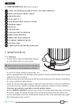
5.1) Topping up the hydraulic oil
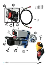
(Ref. to Figs. 7 and 8, page 36)
Periodically check, at least every 6 months, the oil level in the pump.
– Position the pump on its base on a fl at surface.
– Completely discharge the oil pressure by pushing the pressure release button (PS).
– Remove cap (TL) and check the level of the oil, if necessary
slowly add oil
.
NEVER REFILL OVER THE MAXIMUM LEVEL to leakage during operation.
–
When refi lling is fi nished replace the cap (TL).
Should it be necessary to remove oil from the reservoir, drain by removing the cap with magnetic
insert (TV) (Fig. 7) located on the bottom of the pump.
Clean cap (TV) of any metallic deposits before replacing it.
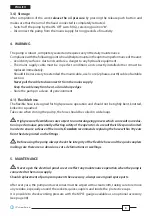
Always use clean recommended oil, see § 1.
Do not use old or recycled oil.
Do not use hydraulic brake fl uid.
Ensure that used oil is disposed of in accordance with current legislation.
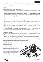
5.2) Protection fuses
The pump is equipped with two protection fuses:
F1
: fuse 10A (5X20) for protection of
electric motor
F2
: fuse 2A (5X20) for protection of
24V control circuits.
In case of replacement, use only
equivalent fuses.
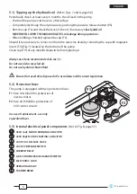
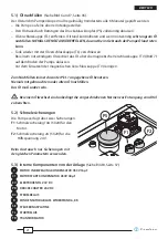
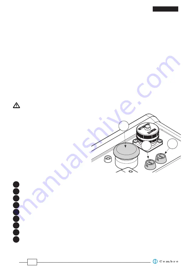
5.3) Internal electrical panel components
(Ref. to Fig. 8, page 37)
450V
16μF
MOTOR RUNNING CAPACITOR
450V
40μF
MOTOR
STARTING
CAPACITOR
24
V
DC
OIL
RELEASE
VALVE
24
V
DC PRESSURE SWITCH
CURRENT RELAY
6,8 K
CONDENSER
DISCHARGE
RESISTOR
ELECTRONIC
CARD
OPERATING
RELAY
TRANSFORMER
F2
F1
PS
C
C1
EV
PR
RC
R
SE
TL
TR


