background image

14

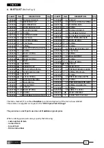
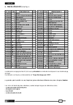
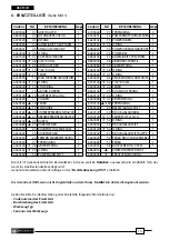
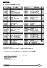
6. ERSATZTEILLISTE 

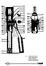
 (Siehe Bild 1)

Die mit (

) gekennzeichneten Bestandteile sind jene, welche 

Cembre 

auszuwechseln empfiehlt, falls das 

Gerät in seine Bestandteile zerlegt wird. 
Genannte Einzelteile sind auf Anfrage in der 

“Ersatzteilpackung HT45”

 erhältlich.

Die Garantie verfällt, wenn nicht Originalteile aus dem Hause  

Cembre

 in das Gerät eingebaut werden.

Geben Sie bitte bei der Bestellung aller Ersatzteile folgende Informationen an:

-  Codenummer des Ersatzteils
-  Beschreibung des Ersatzteils
-  Werkzeug Typ
-  Seriennr. des Werkzeugs

DEUTSCH

Codenr.

Teil

BESCHREIBUNG

Menge

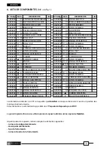
 6090060    01  GRIFFHALTER 

1

 6800040    02  ÖLTANKVERSCHLUß 

1

 6720020    03  ÖLTANK 

1

  6480065   

04  GUMMIGRIFF HAUPTARM 

1

  6900601      05  ANSAUGSCHRAUBE 

1

  6360250    

  06   O-RING 

1

  6641020    

  07   KUPFERSCHRAUBE 

1

  6740100    

  08   5/32" KUGEL 

1

  6520160    

  09   ANSAUGFEDER 

1

  6740120    

  10   7/32" KUGEL                              1

  6520200    

  11   FEDER                     

1

 6340590    12  KUGEL POSITIONIERUNGSSCHRAUBE 1
  6360300    

  13   O-RING                            

1

 6040240 

 14  STÜTZRING 

1

  6160221     

15  GRUND KÖRPER                        1

  6780140    

  16   KOPFBEFESTIGUNG 

1

  6620220     

17  KOLBEN 

1

  6520360    

 18  FEDER 

1

  6900020    

  19   SCHRAUBE    

1

  6520380    

  20   UNTERER PREßEINSATZHALTER   1

  6780360    

  21   OBERER PREßEINSATZHALTER     1

  6370240    

  22   HAKEN 

1

  6520480    

  23   HAKENFEDER 

1

  6040500     

24   KOLBENSCHLIESSDECKEL 

1

  6520025       25  KOLBENFEDER 

1

  6780255     

26  PRESSEIN. FEDERBEFESTIGUNG 1

 6700060    27  SPRENGRING 

1

  6040100    

 28  ABSTREIFRING 

2

  6360161    

 29  O-RING 

1

 6560262    30  PUMPENARMSTIFT 

2

Codenr.

Teil

BESCHREIBUNG

Menge

 6700060     31  SPRENGRING 

  6520401        32   PUMPARMÖFFNUNGSFEDER 1
  6620102        33   PUMPKOLBEN 

1

  6360161    

 34  O-RING 

1

  6080040        35   PUMPKOLBENLENKBUCHSE 1
 6480180     36  PUMPARM 

1


6380200      37  GUMMIGRIFF PUMPARM 

1

  6895020        38   ÜBERDRUCKVENTIL 

1

  6040080    

 39  ABSTREIFRING 

1

  6360140    

 40  O-RING 

1

  6360022    

 41  O-RING 

1

 6800020     42  DRUCKKONTROLLANSCHLUSS 1
  6740120    

  43   7/32" KUGEL 

1

  6520520    

  44   FEDER 

1

  6600100        45   KUGELHALTERUNG 

1

  6360140    

 46  O-RING 

1

  6040080    

  47   ABSTREIFRING 

1

  6700140  

48 SPRENGRING 

2

 6560360     49  BEFESTIGUNGSSTIFT 

2

  6440100        50   DRUCKABLAßHEBEL 

1

  6760100    

  51   FEDERSTIFT Ø 3x16 

1

  6361881    

  52   O-RING                                     

1

  6020020        53   DRUCKABLAßSTIFT 

1

  6360120    

 54  O-RING 

1

  6900640        55  DRUCKABLAßSTIFTKAPPE        1
  6600020        56   FEDER DRUCKABLAßHEBEL     1
  6520280        57  FEDER 

1

  6232018        58   AUFKLEBER (TG. 0355)             1
  6860010     

  VORMONTIERTER KOPF

  6000003       

 ERSATZTEILPACKUNG 

Summary of Contents for HT45

Page 1: ... COMPRESION UTENSILI OLEODINAMICI DA COMPRESSIONE HT45 HT45 E OPERATION AND MAINTENANCE MANUAL NOTICE D UTILISATION ET ENTRETIEN BEDIENUNGSANLEITUNG MANUAL DE USO Y MANTENIMIENTO MANUALE D USO E MANUTENZIONE Certified Environmental Management System Certified Occupational Health Safety Management System Certified Quality Management System 13 M 036 ...

Page 2: ...e peligro Durante l utilizzo mantenere le mani fuori dalla zona di pericolo 2 Always close the tool head correctly and securely S assurer toujours de la parfaite fermeture de la tête Immer darauf achten dass der Kopf richtig verriegeit ist Asegurarse siempre de que la cabeza está correctamente cerrada Assicurarsi sempre della perfetta chiusura della testa 3 4 1 2 3 1 4 This manual is the property ...

Page 3: ...he latch 22 and release the upper die holder 21 Insert one die into the upper die holder 21 and one die into the lower die support 26 Also itshouldbeconsideredthat incaseofindentcompression theindentorPA mustbeinserted in the die support 26 whereas the die MA must be inserted in the upper die holder 21 Close the latch Remove the handle holder 01 to release the moveable handle 36 Ensure that the la...

Page 4: ...lease the oil pressure Fit the handle holder 01 3 WARNING The tool is robust and requires very little daily maintenance Compliancewiththefollowingpoints shouldhelptomaintaintheoptimumperformanceofthetool 3 1 Accurate cleaning Dust sand and dirt are a danger for any hydraulic device Every day after use the tool must be cleaned with a clean cloth taking care to remove any residual especially close t...

Page 5: ...ove all air from reservoir and fit cap 02 i Assemble main handle 04 to tool body If the tool continues to malfunction return the tool for service repair as detailed in 5 4 2 Oil top up Every six months check the oil level in the reservoir If necessary to up the oil level to the top lip of the reservoir and remove all air from the reservoir see 4 1 points a b c and e finally complete with operation...

Page 6: ...KING SPRING 1 6780360 21 UPPER DIE HOLDER 1 6370240 22 LATCH 1 6520480 23 LATCH SPRING 1 6040500 24 RAM GUIDING RING 1 6520025 25 RAM SPRING 1 6780255 26 DIE SUPPORT 1 6700060 27 CIRCLIP 1 6040100 28 BACK UP RING 2 6360161 29 O RING 1 6560262 30 MOVEABLE HANDLE PIVOT 2 Code N Item DESCRIPTION Qty 6700060 31 CIRCLIP 4 6520401 32 HANDLE OPENING SPRING 1 6620102 33 PUMPING RAM 1 6360161 34 O RING 1 6...

Page 7: ...tant le levier 22 libérant ainsi le porte matrice supérieur 21 qui s écartera complétement grâce au ressort Insérer délicatement les matrices dans leur logement respectif porte matrice supérieur 21 et porte matrice inférieur 26 Par ailleurs dans le cas d un sertissage par poinçonnage le poinçon PA doit être inséré dans le porte matrice 26 et la matrice dans le sommier 21 Fermer la tête de l outil ...

Page 8: ... voir 2 4 et verrouiller les bras à l aide de la bride 01 3 PRECAUTIONS Cet outil est robuste et ne nécessite aucune préoccupation ou entretien particulier Les recommandations qui suivent sont néanmoins souhaitables pour lui assurer une longévité optimum 3 1 Nettoyage élémentaire Veiller à protéger l outil de la poussière du sable et de la boue qui sont un danger à tout systéme hydraulique Chaque ...

Page 9: ...ant de refermer le réservoir d huile l air doit être complétement évacué Si le niveau d huile est bas un complément doit être fait comme mentionné à 4 2 h Refermer le capuchon 02 i Ensuite remonter le bras principal 04 Dans l éventuel cas où malgré cette intervention l outil ne fonctionnerait pas correctement il est recommandé de le retourner à Cembre pour une révision complète voir 5 4 2 Compléme...

Page 10: ...0 RESSORT PORTE MATRICE 1 6780360 21 PORTE MATRICE 1 6370240 22 CROCHET PORTE MATRICE 1 6520480 23 RESSORT RAPPEL CROCHET 1 6040500 24 ANNEAU GUIDE PISTON 1 6520025 25 RESSORTDERAPPELPISTON 1 6780255 26 SUPPORT PORTE MATRICE 1 6700060 27 CIRCLIP 1 6040100 28 ANNEAU TEFLON 2 6360161 29 JOINT 1 6560262 30 AXE BRAS MOBILE 2 N Code Pièce DÉNOMINATION Q té N Code Pièce DÉNOMINATION Q té 6700060 31 CIRC...

Page 11: ...Halterung ein den oberen Presseinsatz in den Presseinsatzhalter 21 bis er in die Feder einrastet sowie den unteren Presseinsatz ebenfalls in den Presseinsatzhalter 26 einrasten Im Fall einer Dornverpressung muss der Dorneinsatz PA in den unteren Preßeinsatzhalter 26 eingefügt werden Der Preßeinsatz MA muß dementsprechend in den oberen Preßeinsatzhalter 21 montiert werden Schließen Sie den Presskop...

Page 12: ...efestigt 3 HINWEISE Die hydraulische Handpresse ist robust und benötigt keine spezielle Pflege oder Instandhaltung Zur Erhaltung der Garantieansprüche beachten Sie folgende Hinweise 3 1 Pflege Dieses hydraulischeWerkzeug sollte vor starkerVerschmutzung geschützt werden da diese für ein hydraulisches System gefährlich ist Jeden Tag nach der Arbeit sollte das Werkzeug mit einem Tuch von Schmutz und ...

Page 13: ...ten kann es passieren dasWerkzeug nach diesenWartungsarbeiten nicht oder nicht richtig funktioniert In diesem Fall sollte entspr Pkt 5 verfahren werden 4 2 Öl nachfüllen Luftblasen im Öltank lassen sich vermeiden wenn der Tank stets gut gefüllt ist Deshalb sollte alle 6 Monate der Tank kontrolliert und bei Bedarf aufgefüllt werden Dies erfolgt so wie in den Punkten a b c und beschrieben wurde Dana...

Page 14: ...OLBEN 1 6520360 18 FEDER 1 6900020 19 SCHRAUBE 1 6520380 20 UNTERERPREßEINSATZHALTER 1 6780360 21 OBERERPREßEINSATZHALTER 1 6370240 22 HAKEN 1 6520480 23 HAKENFEDER 1 6040500 24 KOLBENSCHLIESSDECKEL 1 6520025 25 KOLBENFEDER 1 6780255 26 PRESSEIN FEDERBEFESTIGUNG 1 6700060 27 SPRENGRING 1 6040100 28 ABSTREIFRING 2 6360161 29 O RING 1 6560262 30 PUMPENARMSTIFT 2 Codenr Teil BESCHREIBUNG Menge 670006...

Page 15: ...a cabeza de la herramienta tirando lateralmente del cierre hasta que la parte superior que sujeta la matriz 22 quede libre y el muelle la abra completamente Inserteporcompletolasmatricesensushuecosrespectivos partesuperiorysoporteinferior 26 Tenerpresente enelcasodecompresiónporpunzonadoqueelpunzónPA debeestarmontadoen el soporte empuja matrices 26 y la matriz MA debe estar montada en el soporte d...

Page 16: ...ente ver Epigr 2 4 y cierre los brazos con la trabilla 01 3 ADVERTENCIAS Esta herramienta es robusta completamente precintada y no require cuidados especiales para obtener un funcionamiento correcto bastará tener algunas precauciones sencillas 3 1 Limpieza adecuada Tenga presente que el polvo la arena y la suciedad en general representan un peligro para toda herramienta hidráulica Tras cada dia de...

Page 17: ...i el nivel de aceite estuviera bajo éste debe completarse como se indica en el Epig 4 2 h Cierre el tapón 02 i Vuelva a ensamblar el brazo principal 04 En el caso inusual de que tras ésta operaciones la herramienta no funcionara correctamente le sugerimos que devuelva la herramienta a Cembre para su revisión Ver Epig 5 4 2 Rellenado de aceite La presencia de burbujas de aire se evita con el depósi...

Page 18: ...NILLO 1 6520380 20 MUELLE BLOQUEO MATRIZ 1 6780360 21 SOPORTE MATRIZ 1 6370240 22 CUÑA SOPORTE MATRIZ 1 6520480 23 MUELLE RETORNO 1 6040500 24 ANILLA GUIA PISTON 1 6520025 25 MUELLE PISTON 1 6780255 26 SOPORTE MATRIZ 1 6700060 27 ANILLA ELASTICA 1 6040100 28 ANILLA DE PLASTICO 2 6360161 29 JUNTA DE GOMA 1 6560262 30 PASADOR BRAZO MOVIL 2 Elem DESCRIPCION C dad N Código Elem DESCRIPCION C dad 67000...

Page 19: ...lo sblocco del supporto matrice 21 Inserire le matrici nelle rispettive sedi la superiore nel supporto matrice 21 quella inferiore nel supporto spingi matrici 26 Tenere presente che nel caso di compressione mediante punzonatura il punzone PA deve essere montato nel supporto spingi matrice 26 e la matrice MA deve essere montata nel supporto matrice 21 Richiudere la testa Liberare il manico mobile 3...

Page 20: ... richiede attenzioni particolari per ottenere un corretto funzionamento basterà osservare alcune semplici precauzioni 3 1 Accurata pulizia Tenere presente che la polvere la sabbia e lo sporco rappresentano un pericolo per ogni apparec chiatura oleodinamica Dopo ogni giorno d uso si deve ripulire l utensile con uno straccio pulito avendo cura di eliminare lo sporco depositatosi su di esso specialme...

Page 21: ... effettuare un rabbocco come indicato al 4 2 h Inserire il tappo 02 i Rimontare il manico fisso 04 Nel caso eccezionale che l utensile anche dopo queste operazioni di manutenzione non funzio nasse correttamente il pistone non avanza o pulsa è consigliabile contattare il più vicino Agente Cembre per la sua completa revisione vedi 5 4 2 Rabbocco dell olio Il serbatoio dell olio deve essere sempre pi...

Page 22: ...ari sono fornibili su richiesta nella Confezione Ricambio per HT45 La garanzia decade qualora vengano utilizzate parti di ricambio non originali Cembre Per ordinare parti di ricambio specificare sempre i seguenti punti numero di codice del componente denominazione del componente tipo dell utensile numero di matricola dell utensile ITALIANO 6090060 01 CINTURINOBLOCCOMANICO 1 6800040 02 TAPPO SERBAT...

Page 23: ... 38 49 50 51 52 53 54 55 56 57 58 05 04 03 02 01 06 07 08 09 10 11 12 13 14 15 16 18 19 20 21 17 FIG 1 LONGITUDINAL SECTION COUPE LONGITUDINALE SCHNITTZEICHNUNG SECCION LONGITUDINAL SEZIONE LONGITUDINALE Serial number Numéro de série Seriennummer Número de serie Numero di matricola ...

Page 24: ... Telefono 030 36921 Telefax 030 3365766 E mail sales cembre com www cembre it Cembre S a r l 22 Avenue Ferdinand de Lesseps 91420 Morangis France Tél 01 60 49 11 90 Fax 01 60 49 29 10 CS 92014 91423 Morangis Cédex E mail info cembre fr www cembre fr Cembre España S L Calle Verano 6 y 8 P I Las Monjas 28850 Torrejón de Ardoz Madrid España Teléfono 91 4852580 Telefax 91 4852581 E mail comercial cemb...

Reviews: