7
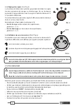
3.3) Torque adjustment
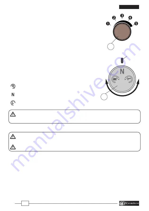
(Ref. to Fig. 3)
The wrench is equipped with a system which allows torque limitation
on tightening and loosening.
For particular requirements it is possible to vary the torque by means
of a 5 position selector (15).
To select different torque values, simply turn the selector in one di-
rection or the other.
Usually selector (15) is set:
–
in the tightening phase
on low torque settings,
pos. 1 - 2 - 3.
–
in the loosening phase
on high torque settings,
pos. 3 - 4 - 5.
3.4) Setting the rotation direction
(Ref. to Fig. 4)
The rotation direction of the shaft is set using the 3 position
selector (07):
: right sense of rotation, to tighten.
: idle position (main shaft gears disengaged).
: left sense of rotation, to loosen.
Adjustment of selector (07) must always be carried out with the motor switched off or
idling, to ensure correct engagement of gears.
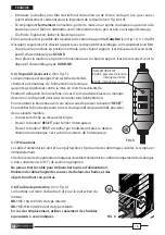
3.5) Operation
Before using the machine always check the correct functioning of the electrical safety
device (see § 3.6). Do not use the machine if the device functions incorrectly.
The machine must only be connected to correctly earthed sockets.
With the impact wrench placed on a flat surface, carry out the following in the order shown:
– Choose the socket appropriate to the work to be carried out and assemble it on the square shaft
(see
§ 3.2
).
– Check that the nominal supply voltage corresponds to the value shown on the machine label
then connect the electric plug (06) to the mains.
– Push the “
RESET
” button of the electrical safety device (08).
– Make sure the torque selector (15) is adjusted to the torque setting required (see
§ 3.3
)
– Set the rotation direction of the wrench (see
§ 3.4
).
– Move switch (13) to “
I
” position.
– Lift the wrench and move it to the work location.
ENGLISH
FIG. 3
07
FIG. 4
15
Reference


