background image

24

Media

7.2 

Device dimensions 

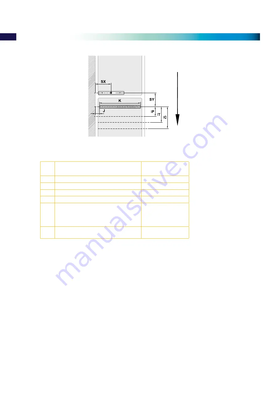
Fig. 19 

Device dimensions

Dim. Designation

Dim. en mm

IP

Distance printhead - peel-off edge

13,5

IC

Distance printhead - cut edge

18,8

IT

Distance printhead - tear-off edge

13,5

J

Distance 1st printing point - material edge

2

K

Print width with printhead 300 dpi

105,6

SX

Distance gap/reflective sensor - 

material edge
i.e. permissible distance of reflex or cut-out 

marks to the material edge

5 - 53

SY

Distance gap/reflective sensor - 

printhead

46,0

Table 9  Device dimensions

Gap sensor 

& Reflective sensor

Printhead

Peel-off edge
Tear-off edge

Cut edge

Feed direction

Summary of Contents for ROLLY 2000

Page 1: ...R PRINTER THERMAL TRANSFER PRINTER 09 M 103 E OPERATION AND MAINTENANCE MANUAL ENGLISH Certified Environmental Management System Certified Occupational Health Safety Management System Certified Quality Management System ...

Page 2: ... 115 V 60 Hz without adjustment Printer size and weight Width Height Length Weight 242 mm 274 mm 446 mm 9 kg MINIMUM SYSTEM REQUIREMENTS PC with dual Core processor or equivalent 2 Gb RAM memory 2 Gb of available space on the hard disc 1280x1024 SVGA monitor resolution Windows XP SP3 VISTA 7 and 8 operating systems USB Port for local installation Ethernet Port for network installation Trademark Ce...

Page 3: ...ls from roll TTL TPM ROLL KM ROLL TTF 12 4 1 1 Removing and installing the core adapters 12 4 1 2 Positioning the label roll on the roll retainer 13 4 1 3 Inserting a label strip into the printhead 13 4 1 4 Setting the label sensor 14 4 1 5 Setting the head locking system 15 4 2 Loading ribbon 16 4 3 Setting the feed path of the ribbon 17 5 Cleaning 18 5 1 Cleaning information 18 5 2 Cleaning the ...

Page 4: ... exclusively for printing suitable materials that have been approved by the manufacturer Any other use or use going beyond this shall be regarded as improper use The manufacturer supplier shall not be liable for damage resulting from unauthorised use the user shall bear the risk alone Usage for the intended purpose also includes complying with the operating manual including the manufacturer s main...

Page 5: ... the printer enables it to be easily disassembled into its component parts X X Send the parts for recycling Following information applies in member states of the European Union X X USER INFORMATION in accordance with Directives 2002 95 EC and 2002 96 EC regarding the reduction of hazardous substances in electrical and electronic equipment including the disposal of waste The Not in the bin symbol a...

Page 6: ...ics 8 Mounting area for accessories incl peripheral connector 9 Navigator pad 10 Display Fig 1 Overview 13 14 15 19 20 17 12 16 18 12 Ribbon guide 13 Printhead locking screw 14 Printhead retainer with printhead 15 Print roller 16 Allen key 17 Printhead locking lever 18 Plate 19 Axle with guide ring 20 Label sensor Fig 2 Print mechanics 2 Installation ...

Page 7: ...er connection socket 25 Slot for PC Card Type II 26 Slot for CompactFlash memory card 27 Ethernet 10 100 Base T 28 2 USB master ports for keyboard scanner or service key 29 USB high speed port 30 Serial RS 232 C port Fig 3 Connections 2 Installation ...

Page 8: ...ard available interfaces and connectors are shown in figure 3 2 3 1 Connecting to the power supply The printer is equipped with a power unit suitable for supply voltages 230 V 50 Hz or 115 V 60 Hz without adjustment Check that the device is switched off 1 Plug the power cable into the power connection socket 6 2 Plug the power cable into an earthed socket 2 3 2 Connecting to a computer or computer...

Page 9: ...r pad Keys Menu Parameter setting Parameter choice Numeric value Return from a submenu Increase the number at the cursor position Jump into a submenu Decrease the number at the cursor position Menu option to the left left Cursor shift to the left Menu option to the right right Cursor shift to the right 1 2 In Linea 6 Start of a selected menu option Hold 2 s Leaving the offline menu Confirmation of...

Page 10: ...is currently processing an active print job Data can be transmitted for a new print job The new print job will start when the previous one has finished Pause Pause and the symbol The printing process has been interrupted by the operator Recoverable error and the type of error and the number of labels still to be printed An error has occurred that can be rectified by the operator without interrupti...

Page 11: ...nting label Printing label Interrupt print job printer goes into Pause state Pause Pause Continue the print job printer goes into Printing label state flashes Recoverable error Continue the print job after rectifying the error printer goes into Printing label state cancel lights Ready Ready Delete internal memory the last label can no longer be reprinted Printing label Printing label Short press g...

Page 12: ...rs 1 3 from the roll retainer 2 6 Re mount the margin stop 4 onto the roll retainer 2 turn ring 5 clockwise so that the arrow 7 points to the symbol and thus fix the margin stop 4 on the roll retainer Installing the core adapters 1 Open cover 2 Turn ring 5 at the margin stop 4 counterclockwise so that the arrow 7 points to the symbol and thus release the margin stop 3 Remove the margin stop 4 from...

Page 13: ...he roll retainer 4 4 Load label roll 3 on the core adapters 4 1 1 on page 12 in such a way that the labels can be inserted into the printhead in the right position The printing side of the labels must be visible from above 5 Re mount the margin stop 1 onto the roll retainer 4 Push the margin stop 1 to the roll until it stops 6 Turn ring 2 clockwise so that the arrow 10 points to the symbol and thu...

Page 14: ...l sensor with tab 3 in such a way that the sensor 1 can detect the label gap or a join reflex or perforation In Figures 12 and 13 there are some examples showing the right positioning of the label sensor 1 depending on the type of material being printed LABEL SENSOR POSITION LABEL SENSOR POSITION LABEL SENSOR POSITION LABEL SENSOR POSITION TTL TPM ROLL ETF ROLL KM ROLL TTF STRIP ROLL TTL Fig 12 Ex...

Page 15: ...IP ROLL TTL Fig 13 Examples of label sensor setting 4 1 5 Setting the print head locking system Attention Usually no adjustment is required so proceed with caution as incorrect setting may move the plungers printhead from its optimum position reducing print quality and possibly damaging the printer The printhead has a three point locking system which is factory set in order to achieve even print q...

Page 16: ...ard when being unwound 4 Hold ribbon roll 3 firmly and turn knob on ribbon supply hub 4 counterclockwise until the ribbon roll is secured 5 Slide suitable transfer ribbon core 1 onto the ribbon take up hub 2 and secure it in the same way 6 Guide ribbon through the print unit as shown in Fig 15 7 Secure starting end of transfer ribbon to the transfer ribbon core 1 with adhesive tape Ensure counterc...

Page 17: ...ew 2 with Allen key and observe the behavior of the ribbon In the direction the inner edge of the ribbon is tightened the outer edge is tightened in the direction The printer is ready for operation when all connections have been made and labels and the transfer ribbon have been loaded Attention Printhead damage can be caused by incorrect handling X X Do not touch the underside of the printhead wit...

Page 18: ...f dirt on the print roller may impair the media flow and the print quality X X Lift the printhead X X Remove media and ribbon from the printer X X Remove deposits with roller cleaner and a soft cloth X X If the roller appears damaged replace it Contact Cembre 5 3 Cleaning the printhead Cleaning frequency every ribbon change Contamination may accumulate on the printhead during printing and adversel...

Page 19: ... 17 Cleaning the label sensor 1 Turn lever 1 counterclockwise to lift the printhead 2 Remove media and ribbon from the printer 3 Press the latch 3 and slowly pull label sensor outward via the tab 4 Ensure that the label sensor cable is not stretched during this operation 4 Clean label sensor and sensor units 2 with brush or cotton swab soaked in pure alcohol 5 Push label sensor back via tab 3 and ...

Page 20: ... runs out Thermal printing driver selected Set the printer to Thermal transfer via driver Printer prints a sequence of characters instead of the label format Printer is in ASCII dump mode Cancel ASCII dump mode Printer transports media but ribbon does not move Ribbon incorrectly inserted Check and if necessary correct the ribbon web and the orientation of the media Incompatible combination of medi...

Page 21: ...rinthead is overheated After pausing the print job will be continued automatically If the fault recurs repeatedly decrease head temperature darkness option or the print speed via driver Invalid setup Error in the configuration memory Re configure printer If error recurs call Cembre Memory overflow Current print job contains too much infor mation e g selected font large graphics Cancel current prin...

Page 22: ...ob Read error Read error when reading from the memory card Check data of the card Backup data reformat card Remove ribbon Transfer ribbon is loaded although the printer is set to direct thermal printing Set the printer to Thermal transfer via driver Structural err Error in the file list of the memory card data access is uncertain Format memory card Unknown card Card not formatted Type of card not ...

Page 23: ...continuous material 25 120 Dl Left margin 0 Dr Right margin 0 E Media thickness 0 025 0 7 F Liner thickness 0 03 0 1 G Thickness of media with liner 0 055 0 8 Q Thickness continuous material 0 03 0 8 V Label feed 6 Small label sizes thin materials or strong adhesive can lead to limitations Critical applications should to be tested before production Note the bending stiffness Material must be flexi...

Page 24: ...f edge 13 5 J Distance 1st printing point material edge 2 K Print width with printhead 300 dpi 105 6 SX Distance gap reflective sensor material edge i e permissible distance of reflex or cut out marks to the material edge 5 53 SY Distance gap reflective sensor printhead 46 0 Table 9 Device dimensions Gap sensor Reflective sensor Printhead Peel off edge Tear off edge Cut edge Feed direction ...

Page 25: ...f reflex mark 3 10 X Distance mark material edge 5 53 Z Distance virtual label front edge actual label front edge X X Adjust software settings 0 up to A recomm 0 Reflex marks must be on the liner side of the material Specification is valid for black marks Recognition of colorued marks may fail u Preliminary tests are needed Table 10 Reflex mark dimensions Feed direction virtual label front edge re...

Page 26: ...ginal cut out 5 8 P Height of cut out mark 2 10 X Distance mark material edge 5 53 Y Sensor recognised virtual label front edge with gap sensor Rear edge cut out Z Distance recognised front edge actual label front edge X X Adjust software settings 0 up to A P Table 11 Cut out mark dimensions Marginal cut out Long hole cut out Rectangular cut out Circular cut out Not recommended Cut out between the...

Page 27: ...act our Area Agent who will advise on the problem and provide the necessary instructions on how to dispatch the printer to our nearest Service Centre if possible attach a copy of the Test Certificate supplied by Cembre together with the printer or if no other references are available indicate the approximate purchase date and serial number 11 Accessories Rolly2000 cutter 990856 fits to front of pr...

Page 28: ...28 This manual is the property of Cembre any reproduction is forbidden without written permission ...

Reviews: