background image

49

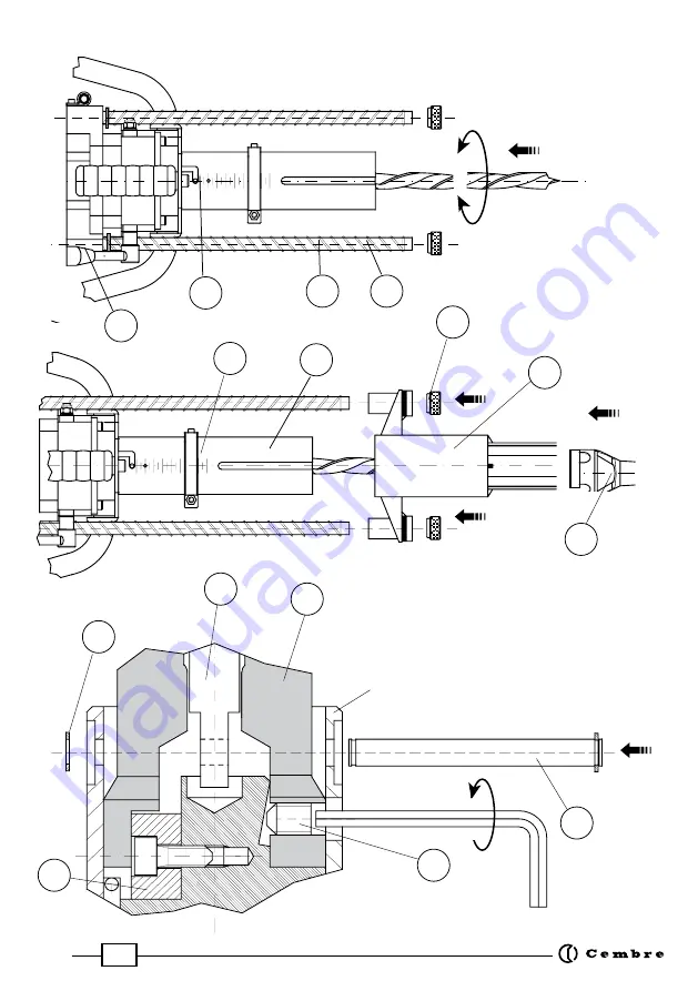
FIG. 2 

SPINDLE CHANGE


CHANGEMENT DE BROCHE


WECHSELN DER SPINDEL


CAMBIO DEL MANDRIL


CAMBIO DEL MANDRINO

15

16

17

18

12

19

20

15

16

17

18

12

19

20

FIG. 1   SETTING THE DRILLING MACHINE  -  PREPARATION DE PERCEUSE   - 

VORBEREITUNG DER BOHRMASCHINE  -  PREPARACION DE LA TALADRADORA  -  

PREPARAZIONE DEL TRAPANO   

15

14

12

10

13

16

Spindle

Broche

Spindel

Mandril

Mandrino

15

16

17

18

12

19

20

15

16

17

18

12

19

20

19

20

21

24

25

22

23

18

09

15

16

17

18

12

19

20

15

16

17

18

12

19

20

Summary of Contents for SD-10E

Page 1: ...TENIMIENTO MANUALE D USO E MANUTENZIONE DRILLING MACHINE FOR WOODEN SLEEPERS PERCEUSE POUR TRAVERSES EN BOIS HOLZSCHWELLENBOHRMASCHINE TALADRADORA PARA TRAVIESAS DE MADERA TRAPANO PER TRAVERSE IN LEGNO SD 10E SD 10E 110 SD 10E2 SD 10E2 110 Certified Environmental Management System Certified Occupational Health Safety Management System Certified Quality Management System ...

Page 2: ...adora Prima di utilizzare il trapano leggere attentamente le istruzioni contenute in questo manuale CONSERVARE QUESTE ISTRUZIONI questo manuale contiene importanti istruzioni per la sicurezza e il funzionamento del trapano Always wear protective goggles and working gloves Avoid wearing clothes that may present a risk to personal safety Porter toujours des lunettes de protection et des gants de tra...

Page 3: ...o tección protezione TPM 200 26 end piece terminaison Endstück terminación terminazione MND spindle broche Spindel mandril mandrino SD 10EN SD 10EN 110 Basic drilling machine perceuse de base Grundbohreinheit taladradora base trapano base SD 10E2 SD 10E2 110 PRM U guard protection Schutzrohr protección protezione TPM 190 24 end piece terminaison Endstück terminación terminazione MND spindle broche...

Page 4: ... single phase double insulation class 2 1800 W protection against overheating caused by a curent overload andagainstunintentionalstartupfollowingadropinvoltage thermal cut out and underpower relay see Fig 7 page 52 18 kg see APPENDIX A page 20 Max drilling capacity Max drilling thickness Speed without load Electric motor Supply Power rating Automatic switch Space dimensions Weight Air Noise Risks ...

Page 5: ...othePRM Uguard Alternative end pieces are available with different diameters to suit different size bushes 1 9 Return springs to assist the retraction of the auger from the sleeper on completion of the drilling operation and to reduce operator effort 2 ACCESSORIES SUPPLIED WITH THE DRILLING MACHINE The machine is supplied complete with Accessories kit code 6001680 containing 1 pc 4 mm allen key 2 ...

Page 6: ... 19 23 24 TPM190 26 19 25 26 TPM200 26 20 25 26 TPM200 26L 20 25 26 TPM220 26 22 25 26 TPM250 31 25 30 31 TPM280 34 28 33 34 3 4 VAL P 6 case Case suitable for storing all the accessories supplied with the drilling machine together with a series of augers 3 5 VAL SD case Steelcasesuitableforstoringboththecompletedrilling machine disassembleddetachableguard andtheVAL P6 accessory case 3 2 TPM end p...

Page 7: ...nd The SD 10E machine is supplied complete with TPM 200 26 end piece should it need to be replaced simply unscrew it by hand and screw on the new end piece suitable for the centreing required Slide the guard bushes onto each shaft and screw a guard knob onto the shaft 4 1 3 Setting the hole depth See Fig 1 Open the lever and loosen the adjuster 24 Position the adjuster to the desired depth on the ...

Page 8: ...ew with 6 mm hex key Press the switch 03 See 4 1 4 Using the main handle of the drilling machine move the trolley over the sleeper to the desired hole position and locate the guard end piece 18 into the bush of the chair Note Foruseofthesupporttrolley refertospecific Serviceand Maintenance Manual 4 3 Drilling To start the motor press the push button 07 Starttodrilltheholebypressingdownlightlyonthe...

Page 9: ...15 Remove circlip 13 and locating pin 14 Slide the spindle from the shaft 10 5 2 Fitting the MND 1 spindle Slide the MND 1 spindle onto the shaft 12 Ensure that the spindle guide 16 is correctly positioned Align the hole on the shaft 10 with the corresponding holes on the spindle 17 Insert the locating pin 14 and fit the circlip 13 Fit and tighten the grubscrew 15 Fit the fixed guard 21 Insert and...

Page 10: ...pose oil Reassemble the springs detachable guard and the two guard retaining nuts 20 Every 50 hours of operation 6 1 2 Checking the bolts Check and retighten all bolts 6 1 3 Changing the brushes See Fig 5 Afterdisconnectingtheelectricplugcheckthedegreeofwearofthebrushes ifnecessaryreplace them by proceeding as follows Unscrew the two screws located underneath the protective covers Remove the two p...

Page 11: ...pring shafts and lubricate if necessary See 6 1 1 7 3 For ease of transportation to prevent accidental damage and to keep the machine dry use the recommended steel storage case ref VAL SD See 3 5 which can also house the detachable guard and the VAL P6 accessory case 8 SPARE PARTS LIST See Fig 6 6001422 01 Brush 2 02 Electric plug 1 03 Automatic switch 1 6001522 04 Handle grip 1 6002522 05 Main ha...

Page 12: ...on the duration of loading times the intervals between exposures and the number of holes made within the space of one working day It is also indicated by way of example that for a worker who uses the SD 10E drilling machine properly for making holes of Ø 18 mm in a 15 cm thick wooden sleeper producing up to 450 holes day the daily personal exposure to the noise due solely to the use of the machine...

Page 13: ...nnement de la perceuse FRANÇAIS 25 mm 200 mm 1600 rpm monophasé double isolation classe 2 1800 W protection contre les surintensités et contre l allumage acciden tel après une chute de tension relais thermique et de tension minimale Voir Fig 7 page 52 18 kg voir APPENDICE A page 20 Capacité max de perçage Profondeur max de perçage Vitesse à vide sur le mandrin Moteur électrique Tension d alimentat...

Page 14: ... de mèches de Ø max 20 mm La terminaison est fournie montée sur la protection PRM U et peut êtrerempla cée en cas de besoin par des terminaisons ayant des diamètres de centrage différents 1 9 Ressorts de rappel éléments de remontée extraction de la mèche hors du bois sans effort pour l opérateur une fois l opération de perçage terminée 2 ACCESSOIRES FOURNIS AVEC LA PERCEUSE La perceuse est livrée ...

Page 15: ...offret VAL SD Robuste coffret métallique pour ranger la perceuse complète avec protection mobile démontée et la mallette des accessoires VAL P6 TYPE ø maxi mèche mm ø de centrage mm ø trou de la selle mm TPM100 18 10 17 18 TPM170 24 17 23 24 TPM190 24 19 23 24 TPM190 26 19 25 26 TPM200 26 20 25 26 TPM200 26L 20 25 26 TPM220 26 22 25 26 TPM250 31 25 30 31 TPM280 34 28 33 34 3 2 Terminaisons TPM int...

Page 16: ...nt d une longueur suffisante pour remonter les pommeaux de protection enfin serrer manuellement ces derniers La perceuse SD 10E est fournie avec sa terminaison TPM 200 26 pour la remplacer il suffira de la dévissermanuellementetvisseràfondlanouvelleterminaisonadéquatepourlecentrageàeffectuer 4 1 3 Réglage de la profondeur de perçage Voir Fig 1 Desserrer la bride 24 de réglage de la course en tiran...

Page 17: ...ctuer engager l élément de centrage de la terminaison 18 dans le trou de la selle Pour l utilisation du chariot support consulter la notice d utili sation et d entretien relative 4 3 Perçage Pour activer le moteur agir sur le bouton de mise en marche 07 Procéder à l exécution de la perforation en effectuant une légère pression initiale sur la perceuse de façon à ce que la mouche fasse prise et com...

Page 18: ...D 1 Introduire la broche MND1 sur l arbre correspondant 12 en l orientant de façon à ce que la languette d entraînement 16 de la broche s engage dans le logement correspondant sur l arbre Aligner le trou situé sur l arbre 10 du levier de secours avec les trous correspondants sur la broche 17 Engager la goupille 14 d accouplement de la broche dans l arbre 10 du levier de secours et la bloquer à l a...

Page 19: ... uniformément de façon à former un film Remonter les ressorts la protection mobile et bloquer l ensemble avec le pommeaux depro tection 20 en serrant à fond Toutes les 50 heures 6 1 2 Verification de la boulonnerie Contrôler et resserrer si besoin toutes les vis de l appareil 6 1 3 Changement des balais Ref Fig 5 Après avoir débranché la prise secteur contrôler l état d usure des balais si leur re...

Page 20: ...gional qui vous conseillera et le cas échéant vous donnera les instructions nécessaires pour envoyer l outil à notre Centre de Service le plus proche Dans ce cas joindre une copie du Certificat d Essai livré par Cembre avec l outil ou à défaut d autres éléments de référence indiquer la date d achat approximative et numéro de série FRANÇAIS 6001422 01 Balai moteur 2 02 Prise de alimentation 1 03 In...

Page 21: ...et des intervalles en bref du nombre de trous percés au cours d une journée de travail Atitred exemple nousindiquonsquesiuntravailleurutiliselaperceuseSD 10Edefaçoncorrecte pour percer des trous Ø 18 mm à l aide d un foret type FS sur une traverse en bois de chêne de 15 cm d épaisseur réalisant 450 trous par jour l exposition au bruit imputable uniquement à l emploi de la perceuse est de 77 1 dB A...

Page 22: ...igungselemente integriert HOLZSCHWELLENBOHRMASCHINE DEUTSCH 25 mm 200 mm 1600 U min Einphasen doppelt isoliert Schutzklasse 2 1800 W Der automatische mit Thermorelais bzw Mindestspannung verse hene Schalter dient als Schutz gegen die durch den Überstrom bedingte Überhitzung sowie gegen den ungewollten Anlauf nach einem Stromausfall siehe Bild 7 Seite 52 18 kg siehe ANHANG A Seite 29 Max Bohrdurchm...

Page 23: ...25 mm Der maximale Bohrerdurchmesser beträgt 20 mm Das Endstück wird auf der Schutzvorrichtung PRM U montiert geliefert und kann im Bedarfsfall mit Endstücken mit unterschiedlichen Zentrierdurchmessern ausgewechselt werden 1 9 Rückzugsfedern Rückzugsfedern zum einfachen Herausziehen der Bohrvorrichtung nach Beenden des Bohrvorganges und dadurch geringe körperliche Belastung des Bedieners durch das...

Page 24: ...StabilerMetallkofferfürdiekompletteSchwellenbohr maschine bewegliches Schutzrohr demontiert und für den Zubehörkoffer VAL P6 TYP Max Bohrer ø mm Zentrierelement ø mm Bohrung ø in der Rippenplatte mm TPM100 18 10 17 18 TPM170 24 17 23 24 TPM190 24 19 23 24 TPM190 26 19 25 26 TPM200 26 20 25 26 TPM200 26L 20 25 26 TPM220 26 22 25 26 TPM250 31 25 30 31 TPM280 34 28 33 34 3 2 Endstücken TPM mit dem St...

Page 25: ...auben gegebenenfalls Schutzrohr gegen die Federn drücken Die Bohrmaschine SD 10E wird komplett mit dem Endstück TPM 200 26 geliefert Soll das Endstück ausgewechselt werden ist es ausreichend es von Hand abzuschrauben und das für die durchzufüh rende Zentrierung geeignete Endstück bis zum Anschlag aufzuschrauben 4 1 3 Einstellen der Bohrtiefe Siehe Bild 1 Anschlagring 24 durch Lösen des Exenterhebe...

Page 26: ...maschinefesthaltenunddenWagengleitenlassen bisdergewünschte Bohrpunkt erreicht wird Die Bohrmaschine mit der Zentrierspitze des beweglichen Endstück 18 in die Rippenplatte der zu bohrenden Holzschwelle stellen Hinweiss Zum Gebrauch des Stützwagens auf die entsprechen de Bedienungsanleitung achten 4 3 Bohrvorgang Die Anlauftaste 07 drücken um den Motor in Betrieb zu setzen Das Loch bohren indem ein...

Page 27: ...ngs welle 10 selbst verbindet herausziehen 5 2 Montage der Spindel MND1 Spindel MND1 in die Antriebswelle 12 stecken Dabei ist auf die richtige Position der Paß federn 16 und der Spindel zu achten Entrieglungswelle 10 undSpindelsoausrichten daßderSicherungsstift 14 montiertwerden kann Sicherungsstift 14 montieren und mit dem Sicherungsring 13 sichern Imbusschraube 15 einsetzen und mit dem mitgelie...

Page 28: ...hrungsstangen verteilen Federn bewegliches Schutzrohr und Rändelmuttern 20 wieder montieren Alle 50 Betriebsstunden 6 1 2 Alle Schrauben und Muttern kontrollieren Alle Schrauben und Muttern kontrollieren und wenn nötig nachziehen 6 1 3 Kontrolle der Kohlebürsten und eventueller Wechsel Siehe Bild 5 Netzstecker Herausziehen Die Bürsten kontrollieren und wenn nötig austauschen wie folgt Die zwei Sch...

Page 29: ...n unsere Gebietsvertretung wel che Sie gerne beraten und Ihnen alle nötigen Informationen zum Einschicken des Gerätes an unseren Hauptsitz geben wird Wenn vorhanden legen Sie bitte dem Gerät das von Cembre mitgelieferte Überprüfungszertifikat bei In Ermangelung dieser Informationen geben Sie bitte an wann Sie das Gerät erworben haben DEUTSCH 6001422 01 Kohlebürsten 2 02 Stecker 1 03 Automatikschal...

Page 30: ... z B angegeben daß für einen Bediener der die Bohrmaschine SD 10E rechtmäßig bei der Durchführung von Bohrungen Ø 18 mm mit einem Hohlbohrer auf einer Eichenholzschwelle mit einer Stärke von 15 cm bei der Durchführung von 450 Bohrungen pro Tag die tägliche persönliche Lärmgefahr die nur der Bohrmaschine zurückzuführen ist gleich 77 1 dB A ist Unter den gleichen Bedingungen ergibt die tägliche Lärm...

Page 31: ...o de la taladradora ESPAÑOL TALADRADORA PARA TRAVIESAS DE MADERA 1 CARACTERÍSTICAS GENERALES 25 mm 200 mm 1600 rpm monofásico doble aislamiento clase 2 1800 W protección contra el recalentamiento provocado por sobrecor rientes y contra la puesta en marcha accidental tras una caída de tensión relé térmico y de mínima tensión véase Fig 7 pag 52 18 kg véase el APÉNDICE A pag 38 Capacidad de perforaci...

Page 32: ...mientos utilizados habitualmente en el sector ferroviario Permite utilizar brocas de perforación con Ø máx igual a 20 mm La termina ción es suministrada montada sobre la protección PRM U y puede ser reemplazada en caso de necesidad con terminaciones que tengan diámetros de centrado diferentes 1 9 Muelles de retorno elementos para subida extracción de la broca de la madera una vez la operación de p...

Page 33: ...ados en el equipamiento de la taladradora y una serie de brocas 3 5 Caja VAL SD Sólidacajametálicaparaguardartantolataladradora completa con la protección móvil desmontada como el estuche VAL P6 con los accesorios TIPO ø max broca mm ø de centrado mm ø taladro placa mm TPM100 18 10 17 18 TPM170 24 17 23 24 TPM190 24 19 23 24 TPM190 26 19 25 26 TPM200 26 20 25 26 TPM200 26L 20 25 26 TPM220 26 22 25...

Page 34: ... protección hasta que salgan de un largo suficiente para volver a montar los capuchones de protección por último apretar a fondo estos últimos manualmente LataladradoraSD 10EessuministradacompuestadeterminaciónTPM200 26 sifuesenecesariosu reemplazamiento bastarácondestornillarlamanualmenteyatornillarafondolanuevaterminación adecuada para el centrado que se desea efectuar 4 1 3 Regulación de la pro...

Page 35: ...ose sobre el punto de perforación deseado introducir el elemento de centrado de la terminación 32 dentro del agujero de la placa metálica que se quiere fijar sobre el la traviesa demadera Nota para la utilización del carro de soporte referirse al corres pondiente Manual de uso y mantenimiento 4 3 Perforación Para activar el motor recurrir al botón de puesta en marcha 07 Proceder a la realización d...

Page 36: ...Insertar el mandril MND1 sobre el árbol mandril 12 orientándolo de manera que la lengüeta de arrastre 16 del mandril se introduzca en el asiento correspondiente en el árbol mandril Alinear el agujero situado en el árbol 10 de la palanca de emergencia con los agujeros co rrespondientes del mandril Insertarelperno 14 deacoplamientodelmandrilenelárbol 10 delapalancadeemergencia y bloquearlo con el ar...

Page 37: ...óvilybloqueartodoelconjuntoconloscapuchones de protección 20 apretando a fondo Cada 50 horas de funcionamiento 6 1 2 Verificación de los tornillos Verificar y volver a apretar todos los pernos tuercas y tornillos 6 1 3 Cambio de los cepillos Ref a Fig 5 Tras desconectar el enchufe de alimentación controlar el estado de desgaste de los cepillos de ser necesario cambiarlos de la siguiente manera Con...

Page 38: ...bol mandril 1 6700050 13 Aro elástico 1 6001494 14 Perno 1 6340140 15 Tornillo M 8x8 fijación mandrill 1 DESCRIPCION N CódigoElemento C dad 7 PUESTA EN REPOSO DE LA TALADRADORA Al término del trabajo poner en reposo la taladradora procediendo de la manera siguiente 7 1 Limpiarcuidadosamentelataladradorasobretodoenlazonadelabrocaquitandoposibles residuos con un trapo limpio eventualmente humedecido...

Page 39: ...ervalos en definitiva del número de taladros que se realizan en el curso de una jornada de trabajo A título de ejemplo indicamos que en el caso de un trabajador que utiliza la taladradora SD 10E de manera apropiada para perforar taladores Ø 18 mm con broca sobre una traviesa de madera de roble de 15 cm de espesor realizando 450 taladros al día la exposición al ruido imputable exclusivamente al uso...

Page 40: ...necessarioalfunzionamentodeltrapano ITALIANO 1 CARATTERISTICHE GENERALI 25 mm 200 mm 1600 rpm monofase a doppio isolamento classe 2 1800 W dotato di relé termico e di minima tensione per la protezione contro il surriscaldamento provocato da sovraccorrenti e contro l avviamento accidentale dopo una caduta di tensione Rif a Fig 7 pagina 52 18 kg Rif APPENDICE A pag 47 Capacità di foratura Spessore m...

Page 41: ...ggioconøest 25mmdainserirenelle corrispondenti forature delle piastre o dei cuscinetti di comune impiego ferroviario Consente l uso di punte di foratura con un ømax di 20 mm La terminazione viene fornita montata sulla protezione PRM U e può essere sostituita in caso di necessità con terminazioni aventi diametri di centraggio differenti 1 9 Molle di richiamo elementi per la risalita estrazione dell...

Page 42: ...ligettaattaaconteneretuttigliaccessorifornitiacorredo del trapano più una serie di punte di foratura 3 5 Custodia metallica VAL SD Robusta cassa metallica per il contenimento sia del trapano completo protezione mobile smontata sia della valigetta VAL P6 porta accessori TIPO ø max punta mm ø centraggio mm ø foro piastra mm TPM100 18 10 17 18 TPM170 24 17 23 24 TPM190 24 19 23 24 TPM190 26 19 25 26 ...

Page 43: ...a sino alla loro fuoriuscita per una lunghezza sufficiente a rimontarvi i pomoli per protezione che devono poi essere serrati manualmente a fondo IltrapanoSD 10EvienefornitocompletoditerminazioneTPM200 26 sefossenecessarialasuasosti tuzione basteràsvitarlaeavvitareafondolanuovaterminazioneadattaalcentraggiodaeffettuare 4 1 3 Regolazione della profondità di foratura Rif a Fig 1 Sganciare tramitelar...

Page 44: ...orare inserire l elemento di centraggio della terminazione 18 entro il foro della piastra metallica da fissare sulla traversa di legno Nota per l utilizzo del carrello di supporto riferirsi al relativo Manuale per l uso e la manutenzione 4 3 Foratura Per avviare il motore agire sul pulsante di avviamento 07 Procedere all esecuzione del foro esercitando una leggera pressione iniziale sul trapano in...

Page 45: ...no 5 2 Montaggio del mandrino MND 1 Inserire il mandrino MND 1 sull albero mandrino 12 orientandolo in modo che la linguetta di trascinamento 16 del mandrino si posizioni nella relativa sede nell albero mandrino Allineare il foro sull albero 10 della leva di emergenza coi corrispondenti fori sul mandrino 17 Inserire il perno 14 di accoppiamento del mandrino all albero 10 della leva di emergenza e ...

Page 46: ...e la protezione mobile poi bloccare il tutto con i pomoli 20 di protezione fissati con le relative viti serrate a fondo Ogni 50 ore di funzionamento 6 1 2 Verifica della bulloneria Verificare e riserrare tutta la bulloneria 6 1 3 Cambio delle spazzole Rif a Fig 5 Dopo aver scollegato la spina di alimentazione controllare lo stato di usura delle spazzole se necessario procedere alla sostituzione op...

Page 47: ...so ed al riparo da polvere umidità ed urti accidentali Perunamiglioreprotezione laCembreconsiglial impiegodell appositacustodiametallica tipo VAL SD ved 3 5 nella quale trovano posto il trapano la protezione mobile smontata dal trapano e la valigettaVAL P6 degli accessori a corredo 8 LISTA DEI COMPONENTI Rif a Fig 6 ITALIANO 6001422 01 Spazzola autoespellente motore 2 02 Spina mobile 1 03 Interrut...

Page 48: ...tessa dipende dalla du rata dei tempi di carico e degli intervalli e quindi in definitiva dal numero di fori che vengono effettuati nell arco di una giornata lavorativa A titolo di esempio si segnala comunque che per un lavoratore che utilizzi il trapano SD 10E in modoappropriatonell esecuzionedifori 18mmconpuntaaverrinatipoFSsutraversainlegno diroverespessore15cm conrealizzazionedi450fori giorno ...

Page 49: ...16 17 18 12 19 20 FIG 1 SETTING THE DRILLING MACHINE PREPARATION DE PERCEUSE VORBEREITUNG DER BOHRMASCHINE PREPARACION DE LA TALADRADORA PREPARAZIONE DEL TRAPANO 15 14 12 10 13 16 Spindle Broche Spindel Mandril Mandrino 15 16 17 18 12 19 20 15 16 17 18 12 19 20 19 20 21 24 25 22 23 18 09 15 16 17 18 12 19 20 15 16 17 18 12 19 20 ...

Page 50: ...Chariot support Stützwagen Carro de soporte Carrello di supporto 28 18 FIG 3 POSITIONING THE DRILLING MACHINE MISE EN PLACE DE LA PERCEUSE POSITIONIEREN DER BOHRMASCHINE COLOCACION DE LA TALADRADORA POSIZIONAMENTO TRAPANO ...

Page 51: ...re Arrettierungsbolzen clavijas de referencia spine di riferimento slot fente Halteschlitz ranura asola 05 FIG 4 MOVING THE MAIN HANDLE DÉPLACEMENT DE LA MANETTE DREHUNG DES HALTEGRIFFES DESPLAZAMIENTO DE EL BRAZO SPOSTAMENTO DEL MANUBRIO ...

Page 52: ... 25 26 23 27 01 02 03 10 11 12 14 13 15 16 15 16 17 18 12 19 20 17 20 18 21 28 29 09 19 04 05 06 07 08 FIG 6 LONGITUDINAL SECTION COUPE LONGITUDINALE SCHNITTZEICHNUNG SECCION LONGITUDINAL SEZIONE LONGITUDINALE ...

Page 53: ... with support trolley DIMENSIONS mm perceuse sur chariot support ABMESSUNGEN mm Bohrmaschine auf dem Stützwagen DIMENSIONES mm taladradora con carro de soporte DIMENSIONI mm trapano con carrello di supporto max 960 1 0 7 5 1 6 5 0 880 4 0 0 ...

Page 54: ...oniques ainsi qu à l élimination des déchets Le symbole poubelle barrée apposé sur l appareil ou sur son emballage indique que le produit à la fin de sa vie utile doit être recueilli séparément des autres déchets La collecte sélective du présent appareil en fin de vie est organisée et gérée par le producteur L utilisa teur qui voudra se défaire du présent appareil devra par conséquent contacter le...

Page 55: ... deshacerse del presente equipo deberá por lo tanto contactar con el fabricante y seguir el sistema adoptado por el mismo para permitir la recogida por separado del equipo que ha concluido su ciclo de vida La adecuada recogida selectiva para el sucesivo envío del equipo dado de baja al reciclaje al tratamiento y al saneamiento ambiental compatible contribuye a evitar posibles efectos negativos sob...

Page 56: ...les cembre co uk www cembre co uk Cembre S p A Via Serenissima 9 25135 Brescia Italia Telefono 030 36921 Telefax 030 3365766 E mail sales cembre com www cembre it Cembre S a r l 22 Avenue Ferdinand de Lesseps 91420 Morangis France Tél 01 60 49 11 90 Fax 01 60 49 29 10 CS 92014 91423 Morangis Cédex E mail info cembre fr www cembre fr Cembre España S L Calle Verano 6 y 8 P I Las Monjas 28850 Torrejó...

Reviews: