background image

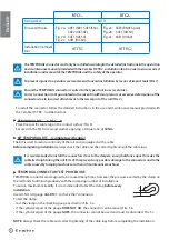
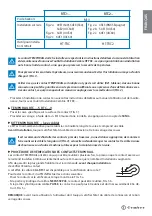
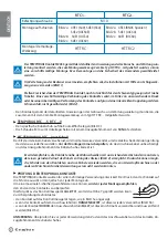
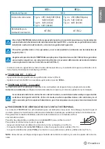
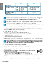
RTC1...

RTC2...

Fixing screw:

M10

For use with rails:

Fig. 2a:    49E1 (S49), 54E3 (S54),  
                  54E2 (UIC54E)
Fig. 2b:    54E1 (UIC54)
Fig. 2c:    60E1 (UIC60)

Fig. 2a:    45E3 (RN45 Spain)                
Fig. 2b:    54E1 (UIC54)
Fig. 2c:    60E1 (UIC60)

Installation/ removal 
tool:

HT-TRC

HT-TRC2


The TEMPORAIL connector must only be installed according to the detailed instructions in the operation 


and maintenance manual provided with the Cembre HT-TRC ..installation tool; in order to ensure correct 


installation and removal of the TEMPORAIL and the safety of the operator.

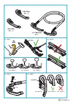
  To prevent injuries to operators we recommend to avoid installation by means of impact tools (FIG.1).


  Ensure the TEMPORAIL connector is suited to the type of rail in use (see table).


Correct connection is not guaranteed in the case of insuffi

    cient pressure or excessive deformation of the 


connector due to incorrect attachment to the lower part of the rail (FIG. 2).

-  To install the connector, follow the detailed instructions in the use and maintenance manual provided with 
  the Cembre HT-TRC... installation tool.


TEMPORAIL RTC...-S   RTC...-V

-  Place the specifi c cable lug on the contact surface (FIG. 3)
-  Secure with the M10 screw and washer, applying a torque ratio of 

50 Nm

.


KIT TEMPORAIL RTC... (complete with cable)

The KIT is used to restore continuity of the rail and is equipped with a cable.

Before completing installation

, always check the cable and the correct tightening of the cable lugs.

  It is recommended to install the connectors close to the sleepers, enough distance apart to make the 


cable lie straight along the rail (FIG. 4); this prevents any possible damage to the connectors and to the 


cable caused by tamping machines or other rail maintenance machines.


TEMPORAIL CONNECTOR TEST PROCEDURE 

TEMPORAIL connector are designed to be reused many times; however, the pressure exerted by the clamp on 
the rail tends to diminish gradually with the increasing number of installations.
To ensure maximum reliability, it is recommended to test the clamp 

before every

installation

.

Use GO-NO GO gauge 

CAL-RTC1

, to check the Y dimension.                    

To test the clamp: 
-  rest the clamp on the checking gauge as shown in FIG. 5 a.
-  if the cylindrical part of the gauge 

DOES NOT GO

, the connector can be reused, FIG. 5 b.

-  if the cylindrical part of the gauge 

GOES

, the connector cannot be used and must be discarded, FIG. 5 c.

NOTE: 

Always check the cable and correct tightening of the cable lugs before completing the installation.

Y

ENGLISH

Summary of Contents for Temporail RTC1 Series

Page 1: ... INSTRUCTIONS INSTRUCTIONS POUR L INSTALLATION MONTAGEANLEITUNG INSTRUCCIONES DE INSTALACIÓN ISTRUZIONI PER L INSTALLAZIONE 16 I 069 TEMPORARY RAIL ELECTRICAL CONNECTION SYSTEM SYSTEME PROVISOIRE DE CONNEXION ELECTRIQUE AU RAIL KONTAKTKLEMME FÜR BAUZUSTÄNDE SISTEMA DE CONEXIÓN ELÉCTRICA PROVISIONAL AL CARRIL SISTEMA TEMPORANEO DI CONNESSIONE ELETTRICA ALLA ROTAIA TEMPORAIL ...

Page 2: ...rew and washer applying a torque ratio of 50 Nm KIT TEMPORAIL RTC complete with cable The KIT is used to restore continuity of the rail and is equipped with a cable Before completing installation always check the cable and the correct tightening of the cable lugs It is recommended to install the connectors close to the sleepers enough distance apart to make the cable lie straight along the rail FI...

Page 3: ...ecommandé d installer les contacts près des traverses à une distance appropriée de manière à faire coulisser le câble le long du rail FIG 4 cela évitera d endommager les contacts et le câble à cause des bourreuses ou d autres machines utilisées pour la maintenance de la voie PROCÉDURE DE VÉRIFICATION DES CONTACTS TEMPORAIL Les contacts TEMPORAIL ont été conçus pour être réutilisés plusieurs fois l...

Page 4: ...igt und das Anzugsdrehmoment des Kabelschuhes korrekt ist Es wird empfohlen die Kontakte nahe der Bahnschwellen mit ausreichendem Abstand zu montieren der einen geraden Verlauf des Kabels entlang des Gleises BILD 4 ermöglicht Dadurch können mögli che Schäden an den Kontakten und am Kabel vermieden werden die von Gleisstopfmaschinen oder anderen Maschinen für die Gleiswartung verursacht werden könn...

Page 5: ...esas a una distancia adecuada para que el cable se deslice a lo largo del carril FIG 4 De este modo se evitarán posibles daños en los contactos y en el cable causados por las máquinas bateadoras o por otras máquinas en uso para el manteni miento del rail PROCEDIMIENTO DE VERIFICACIÓN DE LOS CONTACTOS TEMPORAIL Los contactos TEMPORAIL han sido diseñados para ser utilizados varias veces Sin embargo ...

Page 6: ...apicorda E consigliabileinstallareicontattivicinoalletraversine adunadistanzaadeguatainmododafarscor rere il cavo lungo la rotaia FIG 4 questo eviterà possibili danni ai contatti e al cavo causati dalle mac chine rincalzatrici o da altri macchinari in uso per la manutenzione del binario PROCEDURA DI VERIFICA DEI CONTATTI TEMPORAIL I contattiTEMPORAIL sono concepiti per essere riutilizzati più volt...

Page 7: ... TEMPORAIL RTC TEMPORAIL RTC S 30 mm M10 HT TRC CAL RTC1 FIG BILD 1 FIG BILD 3 FIG BILD 4 FIG BILD 5a FIG BILD 5b FIG BILD 5c 1 1 1 FIG BILD 2a FIG BILD 2b FIG BILD 2c FIG BILD 2 FIG BILD 5 TEMPORAIL RTC V ...

Page 8: ... Calle Verano 6 y 8 28850 Torrejón de Ardoz Madrid España Teléfono 91 4852580 Telefax 91 4852581 E mail comercial cembre es www cembre es Cembre GmbH Heidemannstraße 166 80939 München Deutschland Telefon 089 3580676 Telefax 089 35806777 E mail sales cembre de www cembre de Cembre Inc Raritan Center Business Park 181 Fieldcrest Avenue Edison New Jersey 08837 USA Tel 732 225 7415 Fax 732 225 7414 E ...

Reviews: