background image

OILER MECHANISM ADJUSTMENT 


The oiler is preset at the factory, and should not need a en on, 
but slight adjustment can be made if desired. 

Always ensure 

adequate lubrica on.


The jet is screwed in to be level with the end of the body. 
Tightening clockwise will reduce oil 

fl

ow, and unscrewing an

clockwise will increase the oil 

fl

ow. 


Lubricator performance is visible in the oil container as agita on of 
the oil during saw opera on. (bubbles present in the oil) If no 
agita on is observed, reset the oiler. 
 

PEDESTAL CLEARANCE WHEN REFITTING 


The pedestal, Item 24 (Part No 9344) must always be central to the 
bore of the front end. To ensure this, set  clearance between the 
larger diameter blade grip sec on to be 0.025” (0.64 mm) above 
the body. 


Check for free movement in the nosepiece, without any hard 
contact ,  which would cause wear and loss of power. 
 

REPLACEMENT OF BLEED TUBE 


Fit tube Item 28 (Part No. 93412) and loosely 

fi

t two bleed screws 

Items 29 (Part No. 5056) Replace the nosepiece, and set one bleed 
screw level with the surface. 


Set the machine running which will sound  and feel uneven,  ghten 
the second bleed screw slowly un l the tool runs smoothly. 


REPLACEMENT OF PISTONS


Eventually the pistons will wear, but oversize pistons can be 

fi

ed 

at the factory, resul ng is an ‘as new’ performance. This can be    
repeated several  mes before the bore is worn beyond repair.


Summary of Contents for JP901

Page 1: ......

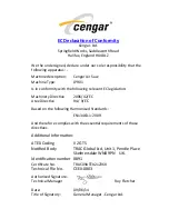
Page 2: ... Machinery Direc ve 2006 42 EC Atex Direc ve 94 9 EC Based on the following Harmonised Standards EN13463 1 2009 And therefore complies with the essen al requirements of those direc ves Addi onal Informa on ATEX Coding II 2G T5 No fied Body TRAC Global Ltd Unit 1 Pendle Place Skelmersdale WN8 9PN U K Iden fica on number 0891 Cer ficate No TRAC09ATEX21236X Technical File No CEEX 0803 Authorised Sign...

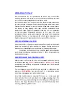
Page 3: ...ca on 10 000 strokes per minute 9 mm 0 116m3 minute 5 6 Bar 1 6 Kgs 270 mm 70 mm 40 mm 6 5 m s2 typical 9 1 m s2 Max 68 6 db 78 0 db CE II 2G T5 X Cengar Air Saw Model JP 901 We recommend normal safe working prac ces should be followed as per the Health and Safety at Work Act or the appropriate Na onal and State Laws We recommend that eye protec on be worn ...

Page 4: ...n inhibitors Incorrect oils if used will soon break down forming a sludge which will slow and eventually stop the ac on of the saw See maintenance details INSTALLATION OF BLADES Before a emp ng to insert or change a blade ensure that the air supply is isolated by opera ng the isola on valve provided Loosen the retaining grub screws with the key provided insert blade through nosepiece so that the t...

Page 5: ...ontact area of the blade on the work piece be quenched with coolant or water during cu ng to dissipate any heat which may be created by the cu ng process An sta c conduc ve air hose must be used with adequate earth bond con nuity resistance below 1 ohm to ground any electrosta c charges MAINTENANCE AND GENERAL HINTS Always ensure sufficient oil in the tool especially when the saw is in constant use ...

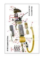
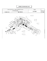
Page 6: ...JP901 Exploded View ...

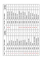
Page 7: ...1 5007 Starter Seal 1 7 5045 Nosepiece 1 20 50412 Screws Nosepiece 2 8 2253 Piston Rear 1 21 9343 Silencer Steady 1 9 2252 Piston Front 1 22 54200 Screws Front end 5 10 9340 Gasket Front 1 23 9338 Seal Top Cover 2 11 9333 Trigger 1 24 9344 Pedestal 1 12 50034 Valve in Handle 1 25 5068 Blade Grip Screws 2 13 2257 Oil Cup 1 26 5206 Seal Oil Cup 1 14 9332 Oiler 1 27 5108 Seal Various 3 15 54500 Screw...

Page 8: ...CEMENT OF TRIGGER VALVE PART NO 50034 To replace the trigger valve loosen the six main screws securing the valve block but do not remove this will allow the trigger bar to be drawn out revealing the valve Replace the valve un l it is level with the top of the hole refit the trigger bar and finger ghten screws Reconnect air supply and check opera on of trigger No air should flow when released full ...

Page 9: ...ys be central to the bore of the front end To ensure this set clearance between the larger diameter blade grip sec on to be 0 025 0 64 mm above the body Check for free movement in the nosepiece without any hard contact which would cause wear and loss of power REPLACEMENT OF BLEED TUBE Fit tube Item 28 Part No 93412 and loosely fit two bleed screws Items 29 Part No 5056 Replace the nosepiece and se...

Page 10: ...nternal parts with anything other than a clean lint free cloth and M S Cleaner or Cengar Green oil 9 NEVER modify Cengar saws or use non Cengar parts this will invalidate ATEX approval and warranty ALWAYS 1 ALWAYS use Cengar green oil for best results Keeping the saw clean and well oiled will give excellent reliability and a long life 2 ALWAYS use Cengar Bi Metal Sha erproof blades for safety and ...

Page 11: ... nosepiece 5045 with 5075 to use 19 mm blades Cengar Green Oil GO 9107P Cengar Green Oil 250 ml plas c bo les for all air tools GO 9109 As above in 5 litre container GO 9110 As above in 25 litre container M S Cleaner MS 9105 1 litre General purpose cleaning fluid for air tools MS 9125 50 ml In a dropper bo le Enough for 10 tools Always use plenty of Cengar green oil a erwards Nosepiece 5045 Replac...

Page 12: ...377161 enquiries cengar com www cengar com SERVICE We offer a full factory repair and refurbishment service for Cengar Saws normally within 5 working days Quota ons at no charge can be given before work is carried out DISTRIBUTOR ADDRESS Original Instruc ons Document No MAN901ENG 01 Issue 07 June 14 ...

Reviews: