background image


Page 12 of 25 

8. Installation 

CEG-P10 ~ CEG-P20 micro repeater should be used to cover the area indoor and the humidity and 

temperature of working can affect the 

reliability

 of repeater. So, temperature, humidity, dust, 

interference, power, space requirements and other factors should be considered during installation 

of repeater.


8.1.   Installation Location Requirement 

1)  It is appreciated that the repeater is installed in a cool, dry and ventilated room without erosive gas and 

smoke and without leakage on its proof. 

2)  Besides above, a cool and ventilated wall of which sun-proof and waterproof is expected. 

3)  Besides above, common wall, tower or high pole is ok. 

4)  Installation height should be easy for RF cable wiring, heat dissipation, security and maintenance. 

5)  Have a set of independent and stable power supply. 

6)  Have lightning conducer in the building, tower or high pole with enough strength or stability. 

8.2. Power requirement 

Generally it is AC power supply

and the requirement of AC is 100~264VAC/50±5Hz 

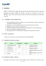
8.3. Installation tools and accessory   

No. 

Name  

Specification 

Quantity  

Remark 

Plastic Expansion Bolt


M5*24 6 

Standard 

accessories 

2 Tapping 

screw


M3*27 4 

Standard accessories 

3 Hanging 

folder


 1 

Standard accessories 

reciprocating drill

   1 

Engineering-owned, punch the 
wall 

5 Shot 

bit 


M3 

Engineering-owned, punch the 
wall 

8.4. Installation of donor antenna 

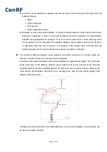
The repeater’s main function is to improve weak RF signals to an area. A simple formula: Input power+ Gain= 

Summary of Contents for CEG-P10

Page 1: ...CEG P10 CEG P20 GSM Series Band selective repeater User s Manual ...

Page 2: ...ATION 10 7 4 REQUIREMENTS FOR ADAPTERS 11 8 INSTALLATION 12 8 1 INSTALLATION LOCATION REQUIREMENT 12 8 2 POWER REQUIREMENT 12 8 3 INSTALLATION TOOLS AND ACCESSORY 12 8 4 INSTALLATION OF DONOR ANTENNA 12 8 5 INDOOR ANTENNA INSTALLATION 17 8 6 REPEATER INSTALLATION 18 8 4 1 Installation Steps 18 8 4 2 Repeater s ports description 19 8 4 3 Accessories selection 20 8 5 REPEATER SETTINGS 20 8 5 1 Switc...

Page 3: ...protection The power supply voltage of repeater should meet the standards of security requirement any operation shall be carried out only after cutting off power in advance Only the professional is authorized for the operation Do not dismantle machine maintain or displace accessories by yourself because in this way the equipment may be damaged or even get an electric shock Do not open the repeater...

Page 4: ...ite few mobile users so the main target is to send coverage to these areas and it will not be cost effect to install a BTS tower therefore a booster is a quite good option Can we not use mobile phones The answer is definitely NO But it might be much more miserable that the communication can t be achieved due to no or weak signals though there is a mobile phone Will your customers stay comfortable ...

Page 5: ...n out of the battery power much more quickly usually the mobile phone gets hot in such status The maximum power level of CEG P10 CEG P20 is 0 01W and it decreases to be maximum 0 003W when reaching server antenna And since the server antenna is installed over the ceiling or onto the wall there are usually more than 3 meter away from the human body 3meter away means at least 40dB propagation loss o...

Page 6: ...during the repeater s operation this repeater has a built in signal oscillation detection circuit to adjust the gain automatically so as to avoid interference to the cellular network also it gets color changing LED s indicate its environmental status the Alarm LED s located on the front of the unit Alarm Low Alarm High will change color from green to orange or red depending on the input power leve...

Page 7: ...ion High integration One board to contain low noise amplifier frequency selection module power amplifier module both uplink and downlink one for all Manual gain control provides a variety of applications MTBF 50000h low failure rate 4 2 Appearance of CEG P10 CEG P20 GSM repeaters Figure 1 the front view colors may differ from real products Figure 2 Side View ...

Page 8: ...system diagram Duplexer The main purpose of duplexer is to combine downlink and uplink to share the same antennas the duplexer is composted of one pair of band pass filter that can not only reject the spurious interference but also increase the isolation of Uplink and Downlink LNA LNA is the first active sub system of the repeater of which low noise and high linearity is requested under strong inp...

Page 9: ...r whip antenna suitable to installed in the center and radiate all direction It is better to use a directional panel antenna or Yagi when the coverage shape is long and narrow corridors long row of houses in two sides tunnels or elevators or rural open space Cables LMR 300 or 400 5D or 8D FB coax cables are recommended Splitters or couplers when the building structure is too complicated or there i...

Page 10: ...Item specification 1 Operating Temperature 25 C to 55 C 2 Storage Temperature 40 C to 80 C 3 Humidity 5 to 85 4 Air Pressure 86 kPa to 106 kPa 7 3 RF technical specification Electrical specification Uplink Downlink Frequency Range 880 915 MHz 925 960 MHz CEG P10 60dB 60dB CEG P15 65dB 65dB Max Gain CEG P20 70dB 70dB CEG P10 10dBm 10dBm CEG P15 10dBm 15dBm Max Output power CEG P20 15dBm 20dBm Band ...

Page 11: ... Output inter modulation 1GHz 12 75GHz 30dBm 3KHz Noise Figure 5dB VSWR 2 0 Group Delay 1 5μs Frequency stability 0 01ppm LED Alarm Standard LED 1 Power Indicator LED Alarm LED 2 ALC 1 5dB Grange ALC 20 25dB Red 7 4 Requirements for adapters SN Item Minimum Typical value Maximum 1 Input Voltage Range 100 V 220 V 264 V 2 Output Voltage Range 47 Hz 50Hz 63 Hz 3 Total Power Consumption 12W ...

Page 12: ...wer or high pole is ok 4 Installation height should be easy for RF cable wiring heat dissipation security and maintenance 5 Have a set of independent and stable power supply 6 Have lightning conducer in the building tower or high pole with enough strength or stability 8 2 Power requirement Generally it is AC power supply and the requirement of AC is 100 264VAC 50 5Hz 8 3 Installation tools and acc...

Page 13: ...e signals from A to E and select a best place that displays full bar signals to install the donor antenna Selection the installation direction of donor antenna The donor antenna shall point to the direction of the tower and it would be much better to keep line of sight Please select the opposite directions for donor antenna and server antenna If donor and server antennas have to be installed in th...

Page 14: ...er For example if the booster gain is 60 dB then the isolation between donor antenna and server antenna should be 75 decibel The minimum distance between donor antenna and server antenna is 10 meters again the direction of donor and server antennas shall be opposite As shown in the below illustration the booster amplifies the signal R and signal T from the tower at the same time If the distance be...

Page 15: ...Page 15 of 25 Installation of panel antenna as donor antenna Installation of wide directional antenna as donor antenna Installation of YAGI antenna as donor antenna ...

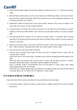
Page 16: ...er level shall be around 50dBm lowest shall be more than 80dBm 2 Test by mobile phone or data card by 3 5 times to make sure Ec Io is more than 7dB and no handovers 3 Ec Io of adjacent carrier shall be 8dB less than that of donor carrier to avoid soft handover The active PN shall be only 1 8 5 Cable layout and connector assembly 1 Keep the type specifications routing direction location and curvatu...

Page 17: ...posed indoor cables in good order Install PVC troughs or tubes if the exposed cables are more than 1 meter long Place small passive RF parts such as power splitter in cable troughs 9 Process both ends of RF coaxial cables as follows Keep the same redundant cable length and keep the length of stripped cables to agree with the corresponding connectors Use a proper force to cut the jacket layer or in...

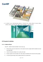
Page 18: ...stallation Steps CEG P10 CEG P20 shall be installed in indoor areas only 1 Drill four holes as per the bracket size on the location where the repeater shall be installed and input expanding plastic 2 Fasten the bracket vertically onto the wall by the screws 3 Hang the repeater onto the bracket The other bracket is installed onto the back side of the repeater 4 Connect the power supply and the cabl...

Page 19: ...eater is installed firmly and repeater alarm LED is green 8 4 2 Repeater s ports description 1 Outdoor port connected with the donor antenna by cable 2 Indoor port connected with server antenna directly or by cable 3 DC IN connected with power supply ...

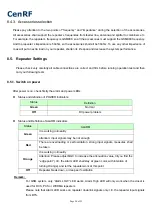
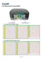
Page 20: ...ests 8 5 1 Switch on power After power is on check firstly the alarm and power LEDs Status and definition of POWER indicators Status and Definition of ALARM indicators Status ALARM It is working in linearity Green attention Input signals may be not enough Red There are overloading or self oscillation strong input signals measures shall be taken It is working in linearity Orange Attention Please ad...

Page 21: ...20dB off off ON off ON 31dB ON ON ON ON ON 10 dB off ON off ON off 21dB ON off ON off ON DIP switch downlink attenuation setting Att 6 7 8 9 10 Att 6 7 8 9 10 Att 6 7 8 9 10 0 dB off off off off off 11dB ON ON off ON off 22dB off ON ON off ON 1 dB ON off off off off 12dB off off ON ON off 23dB ON ON ON off ON 2 dB off ON off off off 13dB ON off ON ON off 24dB off off off ON ON 3 dB ON ON off off o...

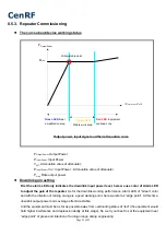
Page 22: ...of Green color and with the intention of turning orange is a good working point here we refer as edge point At this time downlink output power and coverage effect are stable And the equipment must be as far as possible away from overloading status of red the equipment would hold higher interference and depression ability at this stage So we try our best to set the equipment near edge point of gree...

Page 23: ...nger signals until orange intends to turn on or the effect reaches the target At this stage please make sure Orange color is not generated by self oscillation Please take off the server antenna to test if it is self oscillation or not if the Orange turns to be Orange it is self oscillation if it stays as Orange it is not self oscillation Uplink gain setting Standard uplink attenuation values downl...

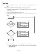
Page 24: ...necessary to add one or more antenna to enhance the coverage of special areas Remark Reduce the attenuation values at the same time must ensure the isolation Increase the output power recommended ways adjust the donor antenna increased input signal strength Test coverage 1 Mobility Service antenna 2 increase the number of service antenna 3 reduce the attenuation values 4 increase the output power ...

Page 25: ... than 10 meters The following measures can also be tried Use the roof of the building to enlarge the isolation Please try to place the donor antenna and server antenna in different floors Use some obstacles Such as wall 2 The repeater s power is on but the phone is not connected into the network and still can not communicate Reason 1 There are loose or wrong connections in the repeater system Solu...

Reviews: