ICS Smart Indoor Repeater
CenRF Communications Limited
www.cenrf.com
Page 7 of 13
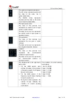
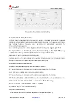
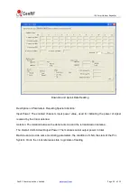
The uplink and downlink indications:
The UP Arrow represents uplink and
the data on the same row is
uplink-related data;
The
DOWN
Arrow
represents
downlink and the data on the same
row is downlink-related data;
The input power value:
The data on the previous row
represents the electric level of input
power in uplink channel;
The data on the next row represents
the electric level of input power in
downlink channel.
The gain value:
The data on the previous row
represents the set gain of uplink
channel;
The data on the next row represents
the set gain of downlink channel.
Isolation:
The data on the previous row
represents
the
environmental
isolation of uplink channel;
The data on the next row represents
the
environmental
isolation
of
downlink channel.
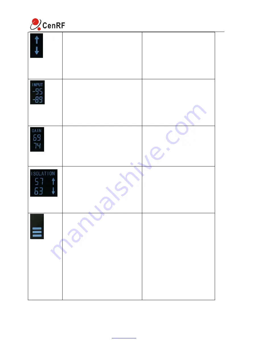
The Progress Bar in the right has 6
bars in total:
1.
For the GSM system, upon
startup of module, in the process
of frequency search, the Progress
Bar will roll circularly.
2.
For the GSM system, if the
frequency search failed, flashing
for alarm would occur.
3.
During the normal operation, the
number of bars indicates the
condition of current working
environment.
The condition of current working
environment:
1 bar: 19~25 dB;
2 bars: 16~20dB;
3 bars: 11~15dB;
4 bars: 6~10dB;
5 bars: 0~5dB
6 bars:
<
0dB

