Steering System
Centaur Service Manual
Ontario Drive & Gear Limited www.centaur8x8.ca
(519) 662-2840 FAX (519) 662-2421
ST-6
ST-6
12. Remove the steering wheel cover to access the locknut that fastens the steering wheel to
the threaded end of steering tube.
Photo ST-7
Slip the steering wheel off the shaft.
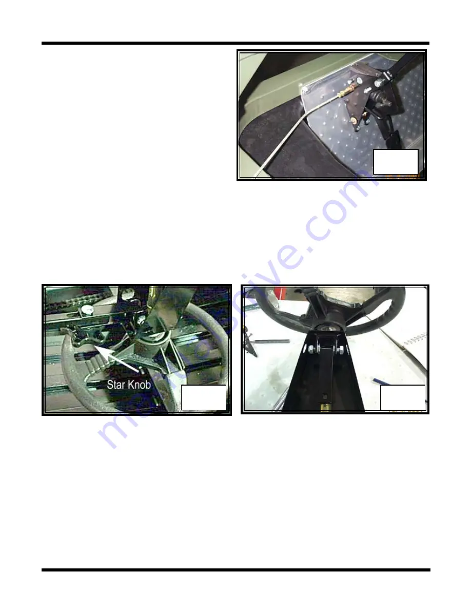
8. Loosen the brake line fitting at the master
cylinder a few turns. Do not completely
free it from the master cylinder.
Photo
ST-4
At the time of production, the
brake line is attached first to the master
cylinder, then bent and formed to the
upper frame assemblies. This tends to
create tension on the brake line into the
master cylinder that can only be released
by removing the 4 fasteners securing
the steering assembly to the bent front
floor plate. Once the assembly has been
unfastened, the brake line fitting should
thread out by hand.
10. Remove the steering wheel and column from the lower adjuster assembly by un-
threading the plastic star knob from the carriage bolt.
Photo ST-5
ST-4
ST-5
11. Detach the steering column from the adjuster assembly plate by removing the bolt, flat
washers, and locknut that secure it together.
Photo ST-6
ST-6
9. Remove the steering assembly from the cab.
Refer to supplement page
ST-6(A)
at the end of this section.
On vehicles manufactured from S/N 0301191:
13. Disassemble the steering column
Summary of Contents for 2001 950
Page 2: ......
Page 4: ......
Page 353: ......
Page 413: ......
Page 416: ...saue Axial Piston Pumps Motors and Transmissions Technical Information Series 70 15 Series ...
Page 429: ...14 saue Axial Piston Pumps Motors and Transmissions Series 70 15 Series Notes ...
Page 447: ...31 saue Axial Piston Pumps Motors and Transmissions Series 70 15 Series Notes ...
Page 449: ......


