16
saue
Axial Piston Pumps, Motors, and Transmissions
Series 70 / 15 Series
General Technical Specifications (Continued)
Allowable Pump Input Shaft Side Loads
The following graphs assume that a self tensioning
device is used to supply tension to the belt, and that
the belt tension is proportional to the amount of torque
required to turn the shaft. Since torque is proportional
to the system pressure generated, belt tension can be
determined by knowing the operating system pres-
sure and the pitch diameter of the sheave.
Typical self tension devices apply five times the
tension to the tight side of the belt as is applied to the
loose side of the belt. The following equations can be
used to calculate the belt side load.
Belt Side Load (lbs.) =
3 x T in
Ds
OR
Belt Side Load (lbs.) =
K x P
Ds
Where:
T in
= Maximum Shaft Input Torque in lbf•in.
Ds
= Sheave Pitch Diameter in inches
P
= System Working Pressure in psi
K
= Constant:
0.33 for BDP-10L or BDU-10L
0.68 for BDU-21L
0.48 for 15 Series
The accompanying graph represents the maximum
allowable conditions based upon shaft stress. All
external shaft loads will have an effect on bearing life.
If continuously applied external loads exceed 25% of
the maximum allowable, contact Sauer-Sundstrand
for unit bearing life evaluation.
Temperature and Cooling
The operating temperature of the transmission should
not exceed 180° F (82° C) continuous and 220° F
(104° C) intermittent. These temperature limits apply
at the hottest point in the transmission, which is
normally the case drain.
Heat exchangers may be installed in the case drain
circuit if necessary, and should be sized to keep the
fluid within recommended temperature limits. Testing
to verify that these temperature limits are not ex-
ceeded is recommended.
Cold oil will generally not affect durability of the
transmission components, but it may affect the ability
to start the engine, flow oil, and transmit power. In
general, cold starts may be made at a temperature
30° F (16° C) above the pour point of the fluid. The
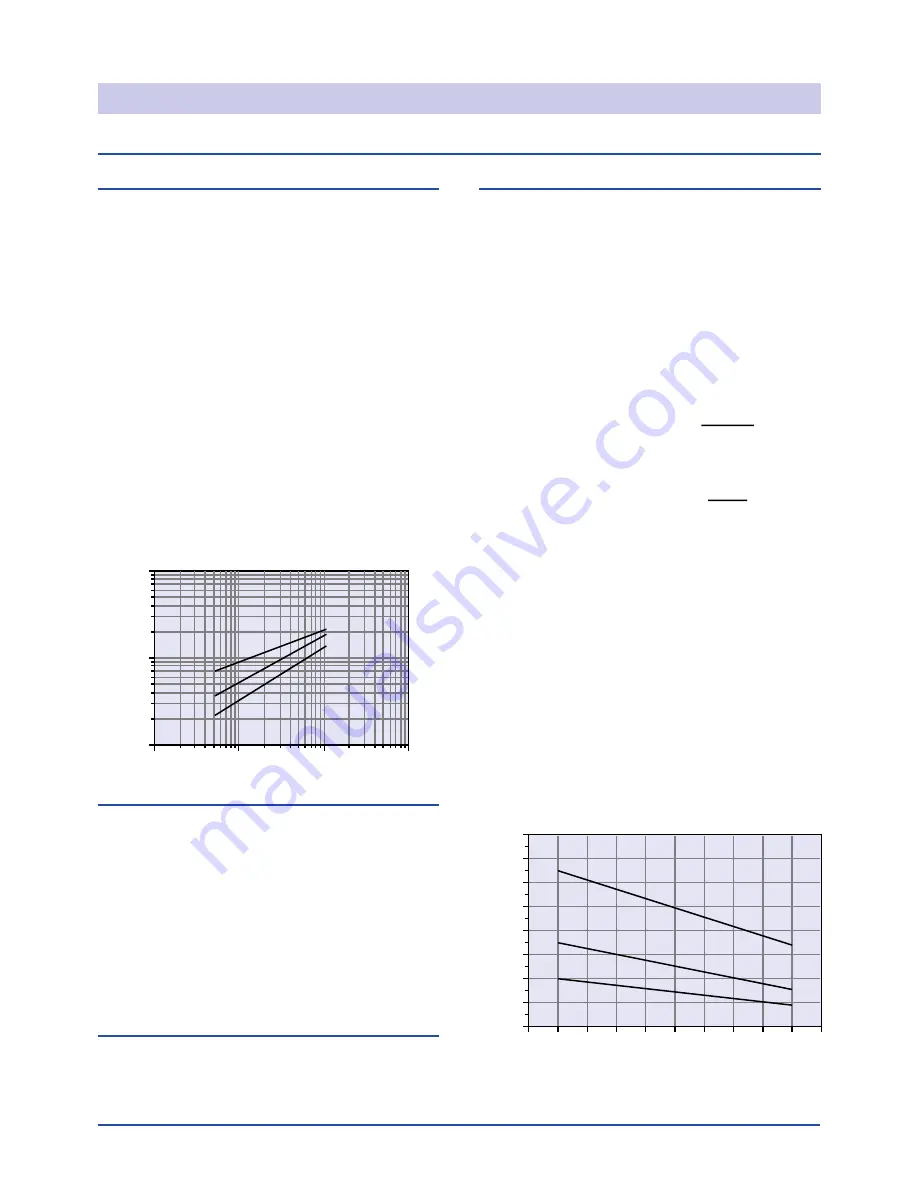
accompanying graph illustrates the relationship be-
tween shaft turning torque at 400 rpm and fluid
viscosity.
0
0.2
0.4
0.6
0.8
1
1.2
1.4
1.6
1.8
2
0
100
200
300
400
500
600
700
800
Side Load — lbsf
Distance from Shaft Seal — in
Maximum Allowable Shaft Loads
15 PV
BDU-21L
BDU/P-10
100 000
10 000
1000
100
10
100
1000
Cold Weather Torque to Turn
(@ 400 RPM and 0° Swashplate Angle)
Oil Viscosity - mm
2
/sec
Torque to Turn — lbf•in
15 PV
BDU-21L
BDU-10L
Auxiliary Mounting Pad (15PV)
The 15 Series pump is available with an optional SAE
“A” mounting pad for mounting auxiliary hydraulic
pumps. Since the auxiliary pad operates under case
pressure, an O-ring must be used to seal the auxiliary
pump mounting flange to the pad.
The 9 tooth spline has a 450 lbf•in (51 Nm) continuous
and 950 lbf•in (107 Nm) maximum torque rating.
These ratings assume a 58 Rc hardness on the
mating pump shaft and 0.53 in. (13.5 mm) minimum
spline engagement. The continuous torque rating is
based on spline tooth wear.
Mounting Flange Loads (15PT)
Subjecting 15 Series tandem pumps to high shock
loads may result in excessive loading of the mounting
flange. Studs are provided at the rear of the unit for
attaching a support bracket.
Summary of Contents for 2001 950
Page 2: ......
Page 4: ......
Page 353: ......
Page 413: ......
Page 416: ...saue Axial Piston Pumps Motors and Transmissions Technical Information Series 70 15 Series ...
Page 429: ...14 saue Axial Piston Pumps Motors and Transmissions Series 70 15 Series Notes ...
Page 447: ...31 saue Axial Piston Pumps Motors and Transmissions Series 70 15 Series Notes ...
Page 449: ......


