Centaur Service Manual Engine System
Ontario Drive & Gear Limited. www.centaur8x8.ca
(519) 662-2840 FAX (519) 662-2421
EN-27
EN-41
EN-45
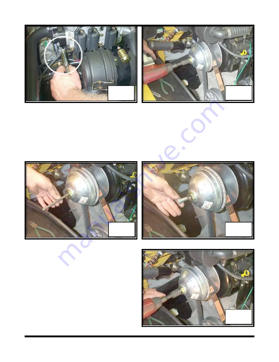
30. Remove the steel rod from the clutch
with a magnet once the clutch has
“popped” from the tapered shaft.
Photo
EN-46
31. Pull the clutch and belt free of the vehi
-
cle.
Photo EN-47
28. Insert a 6” length of 3/8” steel rod into the opening where the previous mounting bolt
was just removed.
Photo EN-43
29. Thread a 9/16”-18 x 1 1/8” bolt back into the clutch and tighten it with an impact. As
the bolt makes contact with the 3/8” steel rod inside the clutch, the clutch is pulled and
released from the tapered shaft of the engine.
Photo EN-44 & 45
EN-44
EN-43
EN-42
23. Pull back the conduit to locate the connector of the green fuel shut off wire from the
carburetor to the harness, and disconnect it. (Gasoline Engine Only)
Photo EN-38
24. Disconnect the coil wiring.
(
Gasoline Engine Only
)
Blue wire
#3 cylinder
,
Orange
wire
#2 cylinder
and the
Red wire
to the
#1 cylinder.
Photo EN-39
The # 1 coil is notably set apart from the
other 2 coils. It is important that these
wires are reconnected in the right order for
correct engine timing and performance
26. Disconnect the ground cable that is
attached to the top clutch guard bolt.
Photo EN-41
27. Remove the bolt and flat washer that
secures the driver clutch to the engine.
Photo EN-42
Summary of Contents for 2001 950
Page 2: ......
Page 4: ......
Page 353: ......
Page 413: ......
Page 416: ...saue Axial Piston Pumps Motors and Transmissions Technical Information Series 70 15 Series ...
Page 429: ...14 saue Axial Piston Pumps Motors and Transmissions Series 70 15 Series Notes ...
Page 447: ...31 saue Axial Piston Pumps Motors and Transmissions Series 70 15 Series Notes ...
Page 449: ......


