CURRENT LIMIT OUTPUTS TERMINAL 3 & 4
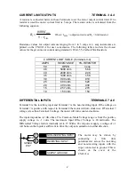
A resistor is connected between these Terminals to set the motor output current limit. If no
resistor is used the motor current limit is 5 amps. The resistor value is calculated from the
following equation:
LIM
LIM
I
I
I
R
−
=
5
)
600
(
Where:
I
LIM
= output current
and
R
I
= limit resistor
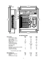
Resistance values for output currents ranging from 1 to 5 amps in ½ amp increments are
printed on the CN0121A for user convenience. The following table also lists the closest
values for the given motor current using standard ¼ Watt, 5% Carbon Film Resistors.
CURRENT LIMIT TABLE (Terminals 3-4)
AMPS RESISTANCE
5%
RESISTOR
5.0 OPEN none
4.5 5400
ohm 5.6K
4.0 2400
ohm 2.4K
3.5 1400
ohm 1.5K
3.0 900
ohm 910
2.5 600
ohm 620
2.0 400
ohm 430
1.5 257
ohm 270
1.0 150
ohm 150
DIFFERENTIAL INPUTS TERMINALS 7 & 8
Terminal 8 is the inverting input and Terminal 7 is the non-inverting input. If the voltage on
Terminal 7 is positive with respect to Terminal 8 the motor will turn clockwise. If Terminal 7
voltage is less than Terminal 8 voltage, the motor will turn counter-clockwise.
The input impedance is 10K ohms. The Common-Mode Voltage range is from the positive
supply voltage to -1 volts. The maximum Input Offset Voltage is 20 millivolts. The
Differential Voltage Gain is internally set to 27. With a 28 volt power supply, a voltage of ±1
volt between the inputs is sufficient to drive the output to saturation in either direction.
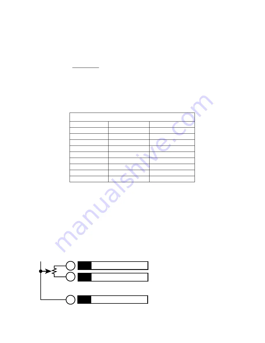
the
CN0121A.
NON-INVERTING INPUT
INVERTING INPUT
SUPPLY GROUND
7
8
SPEED
POT
10K
10
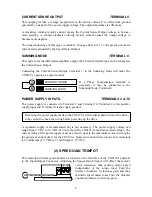
The motor may be driven by
connecting a 10K ohm
potentiometer across the inverting
and non-inverting inputs with the
wiper connected to ground. This is
shown on the cover of
2


