background image


CONTENTS 

 
      TITLE                                                                                                            PAGE 


I. Introduction

…………………………………………………………………………….…..1


II. Specifications

……………………………………………………………………………


1


III. Symbol Definition and Button Location

……………………………….


2


IV. Operation Instructions

…………………………………………….………………


3


4.1 Power-Up

…………………………………………………………………………………....3


4.2 Connection the Thermocouples

………………………………………………………...3


4.3 Selecting the Temperature Scale

……………………………………………………….


3


4.4 Data-Hold Operation

………………………………………………………………………


3


4.5 DataLogger

…………………………………………………………………………………


3


4.6 Clock Setup 

………………………………………………………………………………..


4.7 Recording Interval Setup

……..………………………………………………………….


4.8 Relative Operation

………………………………………………………………………..


4.9 MAX/MIN Operation

……………………………………………………………………….


4.10 Auto Power Off

……………………………………………………………………………4 

4.11 Low Battery Condition 

………………………………………………………………….


4.12 Calibration Point

…………………………………………………………………………


4.13 Digital Output

……………………………………………………………………………..


V. Setup ThermoLog (Thermo DataLogger)

RS232 interface 

software

………………………………………………………………………………………


7


Summary of Contents for 305

Page 1: ...305 Datalogger RS 232 REC POWER UP OPTIONS RANGE 200 C REL HOLD SETUP CLOCK REC INTV C F 328 F 1370 C 2498 F ...

Page 2: ... the Thermocouples 3 4 3 Selecting the Temperature Scale 3 4 4 Data Hold Operation 3 4 5 DataLogger 3 4 6 Clock Setup 3 4 7 Recording Interval Setup 4 4 8 Relative Operation 4 4 9 MAX MIN Operation 4 4 10 Auto Power Off 4 4 11 Low Battery Condition 4 4 12 Calibration Point 4 4 13 Digital Output 5 V Setup ThermoLog Thermo DataLogger RS232 interface software 7 ...

Page 3: ... 400 C 0 5 reading 1 C 400 C 1370 C 0 2 reading 1 C 328 F 200 F 0 5 reading 2 F 200 F 200 F 0 2 reading 2 F 200 F 2498 F 0 3 reading 2 F Note The basic accuracy Specification does not include the error of the probe Please refer to the probe accuracy specification for additional details Sample Rate 2 5 times per second Dimension 184 64 30mm Weight 210g Approx Accessory K Type Bead Probe Battery Car...

Page 4: ...and second y year The Battery is not sufficient for proper operation REC This indicates that the tester is recording If it blinks it indicates the memory is full Button Location K type temperature sensor input connector LCD display ON OFF button Relative readout button Record button MAX MIN function control button HOLD button C F control button Offset calibration screw Digital output connector 11 ...

Page 5: ...eld data is no longer needed one may release the data hold operation by pressing HOLD button again When the meter is under Data Hold operation the REL max min and C F button are disabled when you press REL C F and max min button in HOLD mode there will be two continuous beeps To exit the MAX MIN mode one may press and hold MAX MIN button for two seconds 4 5 DataLogger When one press the REC button...

Page 6: ...Press MAX MIN again MAX and MIN will blink together This means that all these data is updated in the memory and the reading is the present temperature One may press MAX MIN to circulate the display mode among these options When the meter is under MAX MIN operation REL and C F button are disabled when you press REL and C F button in MAX MIN mode there will be two continuous beep To exit the MAX MIN...

Page 7: ...ll return 3 0 5 ASCII 13 Command U Return 32768 bytes Command P Instead of returning all 32768 bytes it only return recorded data Command H Equivalent to one pushing on the HOLD button and no message is returned Command M Equivalent to one pushing on the MAX MIN button and no message is returned Command N Equivalent to one pushing and hold the MAX MIN button for two seconds to exit MAX MIN mode Co...

Page 8: ...full bit7 1 Auto power off enabled 0 Auto power off disabled 4th BYTE first two BCD code of main window value 5th BYTE last two BCD code of main window value 6th BYTE BCD code of month 7th BYTE BCD code of day 8th BYTE BCD code of hours 9th BYTE BCD code of minute 10th BYTE end byte it value is 3 1 nd and 10 th are used to check frame error Appendix Thermo couple probe specification Model Range To...

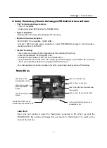
Page 9: ...lect Run 4 Type A SETUP and choose OK then it will copy ThermoLogg exe executable file and help file to your hard disk default is c program files ThermoLog For other operation instruction please refer to the on line help while executing ThermoLog Main Menu Link Test Open Link Test window to search for thermometer connected to PC When you start the THERMOLINK this window will display first and sear...

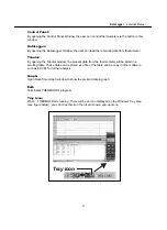
Page 10: ...r window the present data from the thermometer will be listed in a scrolling table These data can be stored as a file or the table can be copy to other software such as EXCEL for further analysis Graph Open Real Time Graph window to show the present data in graph Exit Terminates THERMOLOG program Tray Icon When THERMOLOG is running there will be an icon displayed on the Windows Tray area see figur...

Page 11: ...4 F NO 415 Jung Jeng Rd 238 Shu Lin Chien Taipei Taiwan E Mail center centertek com http www centertek com 305 00 CENTER TECHNOLOGY CORP ...

Reviews: