12
Section 1 - Furnace Installation
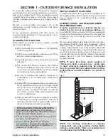
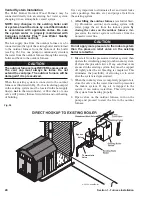
Fig. 8
Gravel or
Small Rock
AUXILIARY BURNER
The auxiliary burner must be installed by a qualified
installer in accordance with local and state and
applicable national codes. Where required by the
authority having jurisdiction, the installation must
conform to the Standard for Controls and Safety Devices
for Automatically Fired Boilers, ANSI/ASME CSD-1.
Each optional burner is accompanied by Central Boiler
instructions and the manufacturer's instructions which
provide the information for proper installation, setup,
adjustment and service.
Upon completion of the installation, the entire installation
must be inspected and all safety shutoff devices tested
according to the manufacturer's instructions.
INSTALLING FUEL TANK & GAS PIPING
If installing a fuel tank, it must be installed by a qualified
installer familiar with all regulations and must conform
to the authorities having jurisdiction, or in the absence
of such requirements, with the NFPA 31, the National
Fuel Gas Code ANSI Z223. or CAN/CGA B149.
All gas piping must conform to the authorities having
jurisdiction, or in the absence of such requirements,
with the National Fuel Gas Code ANSI Z223.1 or CAN/
CGA B149. The line should be dug in underground
to the outdoor furnace and supported to the burner
appropriately.
The pipings should be installed and tested for leaks by a
qualified installer familiar with all regulations.
CIRCULATION PUMPS
NOTE: The direction of water flow is very
important for the proper operation of the outdoor
furnace. Installing a swing check valve in the
return line can prevent possible reverse flow.
Water Flow
For a single building water-to-air heat exchanger system
with a domestic water heater, the direction of water
flow must go from the hot outlet on the outdoor furnace
to the lower side fitting of the domestic water heater
exchanger, to the lower fitting of the heat exchanger
in the plenum of the existing furnace, and then to the
return port of the outdoor furnace.
NOTE: Some systems may have different flow
patterns.
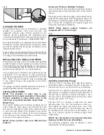
Access to Ports on Outdoor Furnace
Access to the hot and cold outlets is gained by opening
the control panel on the right-hand side of the outdoor
furnace.
The upper ports are the hot supply outlets and the lower
ports are the return inlets. This configuration allows for
mounting the circulation pumps on the outdoor furnace.
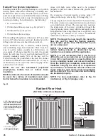
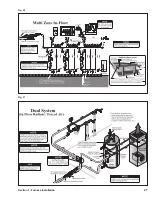
Fig. 9 shows the configuration for proper supply and
return line and pump installations.
NOTE: Pallet Burner outdoor furnaces are
equipped with 1-1/4 inch bungs.
Fig. 9
Installing Circulation Pumps
The Taco 009 is a medium flow, high head pressure
pump that requires an adequate amount of pressure on
the outlet side to prevent the motor from overloading.
The Taco 014 is a high flow, high head pressure pump
that requires an adequate amount of head pressure on
the inlet side to prevent cavitation. Therefore, a Taco
014 may need to be mounted lower near the base of the
furnace, and on the 1-1/4" bung.
The Taco 007 is a medium to high flow, low head
pressure pump. In a very low-resistance system (e.g.,
short length of supply and return lines, only a flat
plate heat exchanger, etc.), the 007 pump may need to
be mounted lower near the base of the furnace or on
the 1-1/4" bung to prevent cavitation at high water
temperatures.
NOTE: See the Hydronic Component Selection
Guide (p/n 2482) for more information.
The following guidelines must be adhered to when
installing the circulation pump(s).


